


Deserial Serial Peripheral Interface (DSPI)
MPC5644A Microcontroller Reference Manual, Rev. 6
Freescale Semiconductor
1301
30.9.4
Combined serial interface (CSI) configuration
The CSI configuration of the DSPI is used to support SPI and DSI functions on a frame by frame basis.
CSI configuration allows interleaving of DSI data frames from the Parallel Input signals with SPI
commands and data from the TX FIFO. The data returned from the bus slave is either used to drive the
Parallel Output signals or it is stored in the RX FIFO. The CSI configuration allows serialized data and
configuration or diagnostic data to be transferred to a slave device using only one serial link. The DSPI is
in CSI configuration when field DSPI_MCR[DCONF] is 0b10.
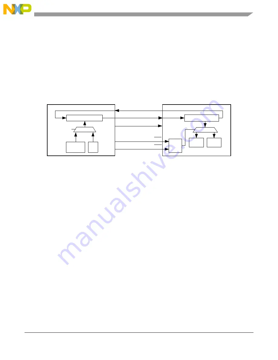
shows an example of how a
DSPI can be used with a deserializing peripheral that supports SPI control for control and diagnostic
frames.
Figure 30-35. Example of system using DSPI in CSI configuration
In CSI configuration the DSPI transfers DSI data based on DSI transfer initiation control. When there are
SPI commands in the TX FIFO, the SPI data has priority over the DSI frames. When the TX FIFO is empty,
DSI transfer resumes.
Two peripheral chip select signals indicate whether DSI data or SPI data is transmitted. The user must
configure the DSPI so that the two DSPI_CTAR registers associated with DSI data and SPI data assert
different peripheral chip select signals denoted in the figure as PCSx and PCSy. The CSI configuration is
only supported in master mode.
Data returned from the external slave while a DSI frame is transferred is placed on the Parallel Output
signals. Data returned from the external slave while a SPI frame is transferred is moved to the RX FIFO.
The TX FIFO and RX FIFO are fully functional in CSI mode.
30.9.4.1
CSI serialization
Serialization in the CSI configuration is similar to serialization in DSI configuration. The transfer
attributes for SPI frames are determined by the DSPI_CTAR selected by the CTAS field in the SPI
command halfword. The transfer attributes for the DSI frames are determined by the DSPI_CTAR selected
by field DSPI_DSICR[DSICTAS].
The Parallel Inputs signal states are latched into the DSPI DSI Serialization Data Register (DSPI_SDR)
on the rising edge of every system clock and serialized based on the transfer initiation control settings in
the DSPI_DSICR. When SPI frames are written to the TX FIFO they have priority over DSI data from the
DSPI_SDR and are transferred at the next frame boundary. A copy of the most recently transferred DSI
Shift Register
SIN
SIN
SOUT
SOUT
SCK
SCK
SSx
PCSx
DSPI Master
External Slave Deserializer
SSy
PCSy
SPI
Frame
Select
Logic
Frame
DSI
Frame
Shift Register
SPI
DSI
TX Priority
Control
TX FIFO
Summary of Contents for MPC5644A
Page 2: ...MPC5644A Microcontroller Reference Manual Rev 6 2 Freescale Semiconductor...
Page 24: ...MPC5644A Microcontroller Reference Manual Rev 6 24 Freescale Semiconductor...
Page 26: ...MPC5644A Microcontroller Reference Manual Rev 6 26 Freescale Semiconductor...
Page 52: ...Introduction MPC5644A Microcontroller Reference Manual Rev 6 52 Freescale Semiconductor...
Page 56: ...Memory Map MPC5644A Microcontroller Reference Manual Rev 6 56 Freescale Semiconductor...
Page 1228: ...Decimation Filter MPC5644A Microcontroller Reference Manual Rev 6 1228 Freescale Semiconductor...
Page 1440: ...FlexCAN Module MPC5644A Microcontroller Reference Manual Rev 6 1440 Freescale Semiconductor...