


Decimation Filter
MPC5644A Microcontroller Reference Manual, Rev. 6
1224
Freescale Semiconductor
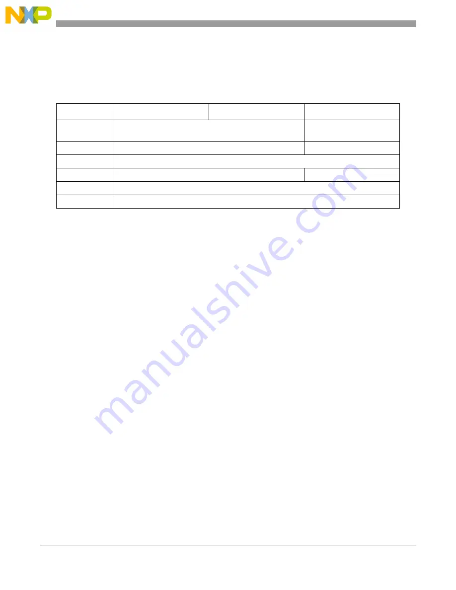
Cascaded blocks can be configured with different filter types (DECFILTER_MCR field FTYPE),
including bypass. The
shows how Decimation Filter features work in each of the Cascade
Mode configurations.
26.6
Initialization information
Following are some simple initialization steps to be done before using the decimation filter block. These
steps assume that the user has already calculated the filter coefficients using a filter design tool
.
26.6.1
Initialization procedure
T
he sequence of steps for the block initialization is as follows:
1. Program the configuration registers DECFILTER_MCR and DECFILTER_MXCR as desired for
your application.
2. Write all filter coefficient registers DECFILTER_COEFn with the previously calculated values.
3. Enable the filter input, writing DECFILTER_MCR bit IDIS = 0.
4. Run a soft-reset cycle if necessary.
5. The module is ready to receive data from PSI or from the device slave-bus interface.
26.7
Application information
26.7.1
eQADC IP as the PSI master block
The system block diagram for the eQADC application is shown in
Decimation Filter receives conversion results generated by the eQADC block. These results can be
generated from eight different ADC setup configurations which are identified by a specific eQADC
Control address within a Conversion command. Conversion commands with Register Address set to zero
use the standard configuration setup. The samples generated by the standard configuration setup are sent
to one of the local eQADC RFIFO buffers. The samples generated by the Alternate Configurations, with
an address from 1–8, can be sent to the internal RFIFO or to the eQADC dedicated slave-bus interface
(Parallel Side Interface PSI) to communicate with the external Decimation Filter IP block or any other
block that can communicate with this interface. A bit field in the Alternate Configuration Control Register
selects the Internal RFIFO or this slave-bus interface as the destination for the conversion result. The
Table 26-31. Features in cascade mode
Feature
Head
Middle
Tail
Prefill
Output and prefill command are forwarded to the next cascaded
block
Effective
Flush
Effective, and forwarded to the next cascaded block
Effective
Decimation
Effective in each block
Timestamp
Forwarded to the next cascaded block
Effective
Enhanced Debug
Effective in each block
Integrator
Effective in each block
Summary of Contents for MPC5644A
Page 2: ...MPC5644A Microcontroller Reference Manual Rev 6 2 Freescale Semiconductor...
Page 24: ...MPC5644A Microcontroller Reference Manual Rev 6 24 Freescale Semiconductor...
Page 26: ...MPC5644A Microcontroller Reference Manual Rev 6 26 Freescale Semiconductor...
Page 52: ...Introduction MPC5644A Microcontroller Reference Manual Rev 6 52 Freescale Semiconductor...
Page 56: ...Memory Map MPC5644A Microcontroller Reference Manual Rev 6 56 Freescale Semiconductor...
Page 1228: ...Decimation Filter MPC5644A Microcontroller Reference Manual Rev 6 1228 Freescale Semiconductor...
Page 1440: ...FlexCAN Module MPC5644A Microcontroller Reference Manual Rev 6 1440 Freescale Semiconductor...