


Enhanced Time Processing Unit (eTPU2)
MPC5644A Microcontroller Reference Manual, Rev. 6
Freescale Semiconductor
973
24.6.5.1
Introduction to worst-case latency
NOTE
In this Appendix the latency calculation and examples refer to old TPU
functions such as PWM, DIO etc. These functions use single action
channels which have single transition and single match functionality. They
are not optimized for the eTPU hardware enhancement which support
various double action modes. These examples are for reference only. New
eTPU functions which are optimized for the new hardware will impose
different latency calculations.
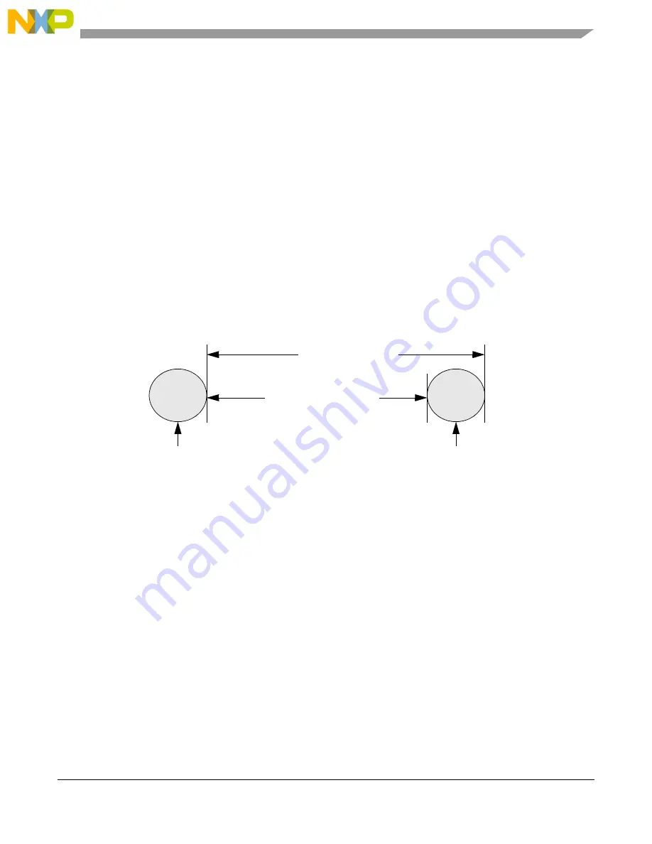
Worst-case latency for a channel is the longest amount of time that can elapse between the execution of
any two function threads on that channel. For example, if in a particular system, channel 5 is running
PWM, the worst-case latency for channel 5 is the longest possible time between the execution of two PWM
threads. The worst-case time includes the time the execution unit takes to execute threads for other active
channels, and other delays described later in this section. Refer to
Figure 24-64. Worst-case latency for PWM
Worst-case latency for a channel depends both on the function running on that channel and on the activity
on other channels. Since the 32 eTPU channels must all share the same execution unit, execution speed of
a particular function varies with each system. The PWM thread response is faster if there are no other
active channels than if other channels are also active. In addition, changing the priority scheme and
channel number assignments can change performance for a function even if the same set of functions are
still active.
Each function is divided into treads, as shown in
(see also
). The eTPU Microengine executes one thread of a function at a time. For example, the Microengine
might execute thread 1 of PWM, then thread 3 of DIO, then thread 2 of PWM, then thread 2 of SM, and
so on. The amount of time the eTPU Microengine grants a function to execute a thread varies with the
number of microcode instructions in the thread.
Since there is only one eTPU Microengine (in each eTPU engine), the eTPU cannot actually execute the
software for multiple functions simultaneously. However, the hardware for each of the channels is
Additional Channel Threads
and other delays.
Worst-Case Latency
for Channel 5
PWM Thread
executed for
Channel 5
Next PWM Thread
executed for
Channel 5
Summary of Contents for MPC5644A
Page 2: ...MPC5644A Microcontroller Reference Manual Rev 6 2 Freescale Semiconductor...
Page 24: ...MPC5644A Microcontroller Reference Manual Rev 6 24 Freescale Semiconductor...
Page 26: ...MPC5644A Microcontroller Reference Manual Rev 6 26 Freescale Semiconductor...
Page 52: ...Introduction MPC5644A Microcontroller Reference Manual Rev 6 52 Freescale Semiconductor...
Page 56: ...Memory Map MPC5644A Microcontroller Reference Manual Rev 6 56 Freescale Semiconductor...
Page 1228: ...Decimation Filter MPC5644A Microcontroller Reference Manual Rev 6 1228 Freescale Semiconductor...
Page 1440: ...FlexCAN Module MPC5644A Microcontroller Reference Manual Rev 6 1440 Freescale Semiconductor...