


Enhanced Queued Analog-to-Digital Converter (EQADC)
MPC5644A Microcontroller Reference Manual, Rev. 6
1128
Freescale Semiconductor
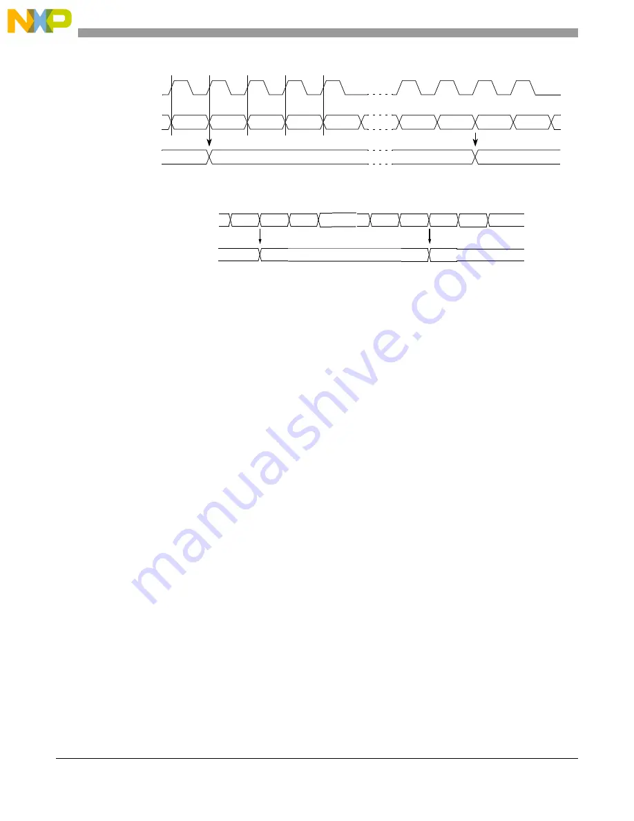
Figure 25-78. Timing Diagram for the STAC Bus and
STAC Client Submodule Output
Every time the selected time slot changes, the STAC client submodule output is updated.
After the slot selection is done and the timebase data is extracted, the STAC client submodule selects 16
bits from the original 24-bit timebase data. These selected bits are the timebase to be used internal to the
EQADC.
25.6.6.5
ADC pre-gain feature
Each ADC can be configured to have a selectable input gain as defined in
Configuration 1-8 Control Registers (ADC_ACR1-8)
. This means the input signal is sampled and the
result is amplified by factor 2, or 4 before the conversion phase. In present implementation of this feature,
the conversion is 1 or 2 ADC clock cycles longer for gain 2 or gain 4, respectively.
25.6.6.6
ADC resolution selection feature
The ADCs conversion resolutions can be 8 bits, 10 bits or 12 bits as described in
Alternate Configuration 1-8 Control Registers (ADC_ACR1-8)
. For conversions at a resolution less than
12, the ADC is executing less operations and the conversion time is smaller. In this ADC, it is verified that
there is 1 ADC clock cycle for each bit of resolution. Therefore, for the same ADC clock frequency, the
ADC sample frequency is higher for lower resolutions.
When a conversion is undertaken at a resolution less than 12, the result is presented by the ADC in right
justified format in the 12-bit input bus e.g.: 0000xxxxxxxx for 8 bits and 00xxxxxxxxxx for 10 bits. The
EQADC inverts the result to left justified format i.e.: xxxxxxxx0000 for 8 bits and xxxxxxxxxx00 for 10
bits. This is because the same calibration coefficients in the MAC can then be used. The left shift operation
is done just after the conversion result enters the EQADC, in the Resolution Adjustment block prior to the
MAC, as illustrated in
TS[02]
STAC bus
(submodule input)
TS[00]
TS[01]
TS[02]
Time base
(submodule output)
TS[01]
xx
The SRV bits are set to capture TS[01].
TS[03]
TS[00]
TS[03]
TS[00]
TS[01]
System clock
TS[01]
STAC bus (REDC input)
TS[00] TS[01] TS[02]
1. Maximum of 16 time slots (TSn)
NOTES:
TS[01]
TS[00]
TSn1
TS[02]
Time base (REDC output)
TS[01]
TS[01]
xx
2. The SRV bits capture TS[01]
Summary of Contents for MPC5644A
Page 2: ...MPC5644A Microcontroller Reference Manual Rev 6 2 Freescale Semiconductor...
Page 24: ...MPC5644A Microcontroller Reference Manual Rev 6 24 Freescale Semiconductor...
Page 26: ...MPC5644A Microcontroller Reference Manual Rev 6 26 Freescale Semiconductor...
Page 52: ...Introduction MPC5644A Microcontroller Reference Manual Rev 6 52 Freescale Semiconductor...
Page 56: ...Memory Map MPC5644A Microcontroller Reference Manual Rev 6 56 Freescale Semiconductor...
Page 1228: ...Decimation Filter MPC5644A Microcontroller Reference Manual Rev 6 1228 Freescale Semiconductor...
Page 1440: ...FlexCAN Module MPC5644A Microcontroller Reference Manual Rev 6 1440 Freescale Semiconductor...