


Enhanced Time Processing Unit (eTPU2)
MPC5644A Microcontroller Reference Manual, Rev. 6
Freescale Semiconductor
983
131 clocks * 25 ns/clock = 3275 ns
Conclusion: In this system configuration PPWA can measure a period or pulse of minimum
3275 ns.
Note that PPWA function optimized for eTPU hardware can use double transition mode to measure
very narrow pulses with one service after the second transition, and latency will affect only the
minimum gap between two input pulses. Also the function threads would have more efficient
coding.
Finding the WCL for DIO on Channel 2
The following shows how to find the WCL for DIO on channel 2.
1. Find the worst-case service time for each active channel. See step 1 of previous examples.
2. Assume channel 2 has just been serviced and that channels 0 and 1 are continuously requesting
service. Using the H-M-H-L-H-M-H time-slot sequence, map the channels that are granted for
each time slot. See
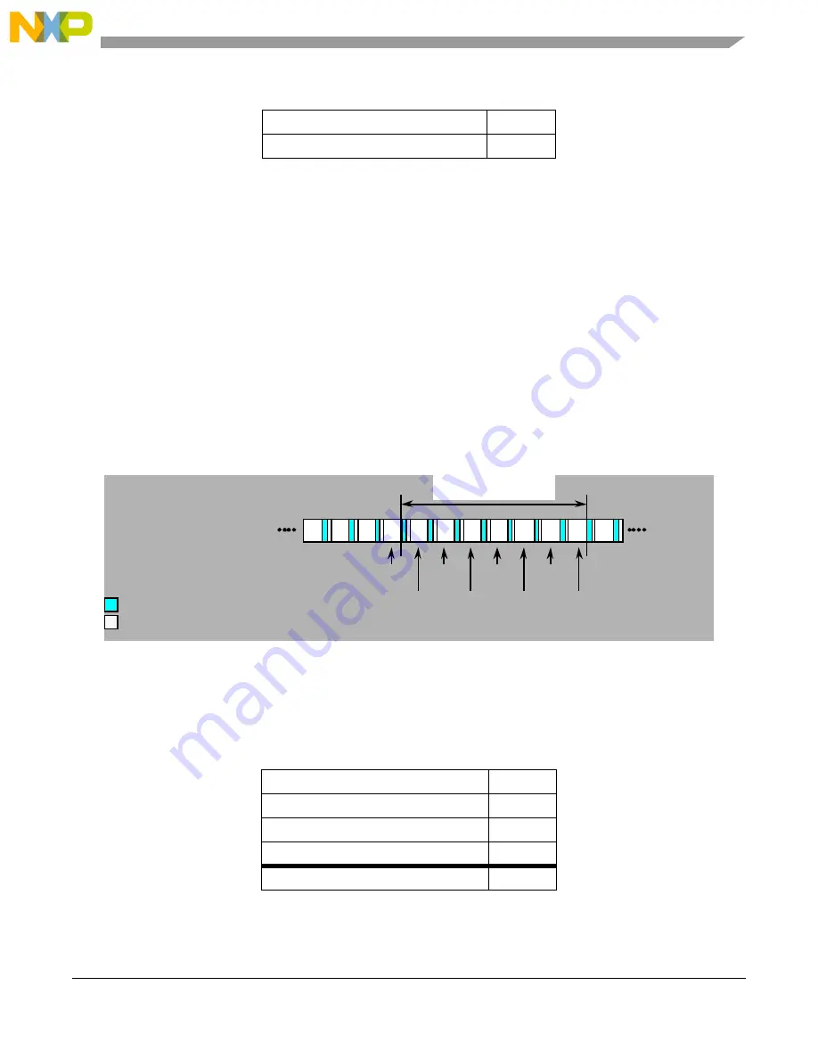
Figure 24-71. Next Servicing for Channel 2
Channel 0 will be serviced four times and channel 1 twice before channel 2 is serviced again.
3. Add time for the ten-clock CPU time-slot transitions and the four-clock NOPs. See
245 clocks * 25 ns/clock = 6125 ns
Four 6-clock time-slot transitions
24 clocks
Total clocks
131 clocks
Table 24-124. Worst-case latency for channel 2
Four Channel 0 worst-case service times 100 clocks
Two Channel 1 worst-case service time
92 clocks
Channel 2 worst-case service time
11 clocks
Seven 6-clock time-slot transitions
42 clocks
Total clocks
245 clocks
Table 24-123. Worst-case latency for channel 1
TPU CH2 WCL TIM
TPU CH2 WCL TIM
CHANNEL 2
SERVICED
WORST CASE LATENCY
CHANNEL 2
H
M
H
L
H
M
H
H
CHANNEL 0
SERVICED
CHANNEL 1
SERVICED
= 10-CYCLE TIME SLOT TRANSITION
= 4-CYCLE NOP INSTRUCTION
CHANNEL 0
SERVICED
CHANNEL 0
SERVICED
M
H
L
H
CHANNEL 1
SERVICED
CHANNEL 0
SERVICED
CHANNEL 2
SERVICED
Summary of Contents for MPC5644A
Page 2: ...MPC5644A Microcontroller Reference Manual Rev 6 2 Freescale Semiconductor...
Page 24: ...MPC5644A Microcontroller Reference Manual Rev 6 24 Freescale Semiconductor...
Page 26: ...MPC5644A Microcontroller Reference Manual Rev 6 26 Freescale Semiconductor...
Page 52: ...Introduction MPC5644A Microcontroller Reference Manual Rev 6 52 Freescale Semiconductor...
Page 56: ...Memory Map MPC5644A Microcontroller Reference Manual Rev 6 56 Freescale Semiconductor...
Page 1228: ...Decimation Filter MPC5644A Microcontroller Reference Manual Rev 6 1228 Freescale Semiconductor...
Page 1440: ...FlexCAN Module MPC5644A Microcontroller Reference Manual Rev 6 1440 Freescale Semiconductor...