


FlexCAN Module
MPC5644A Microcontroller Reference Manual, Rev. 6
Freescale Semiconductor
1431
•
Detection of a dominant bit at the 7th bit (last) of End of Frame field (Rx frames)
•
Detection of a dominant bit at the 8th bit (last) of Error Frame Delimiter or Overload Frame
Delimiter
32.5.8.3
Time stamp
The value of the Free Running Timer is sampled at the beginning of the Identifier field on the CAN bus,
and is stored at the end of “move-in” in the TIME STAMP field, providing network behavior with respect
to time.
Note that the Free Running Timer can be reset upon a specific frame reception, enabling network time
synchronization. Refer to TSYN description in
Section 32.4.5.2, Control Register (CR)
.
32.5.8.4
Protocol timing
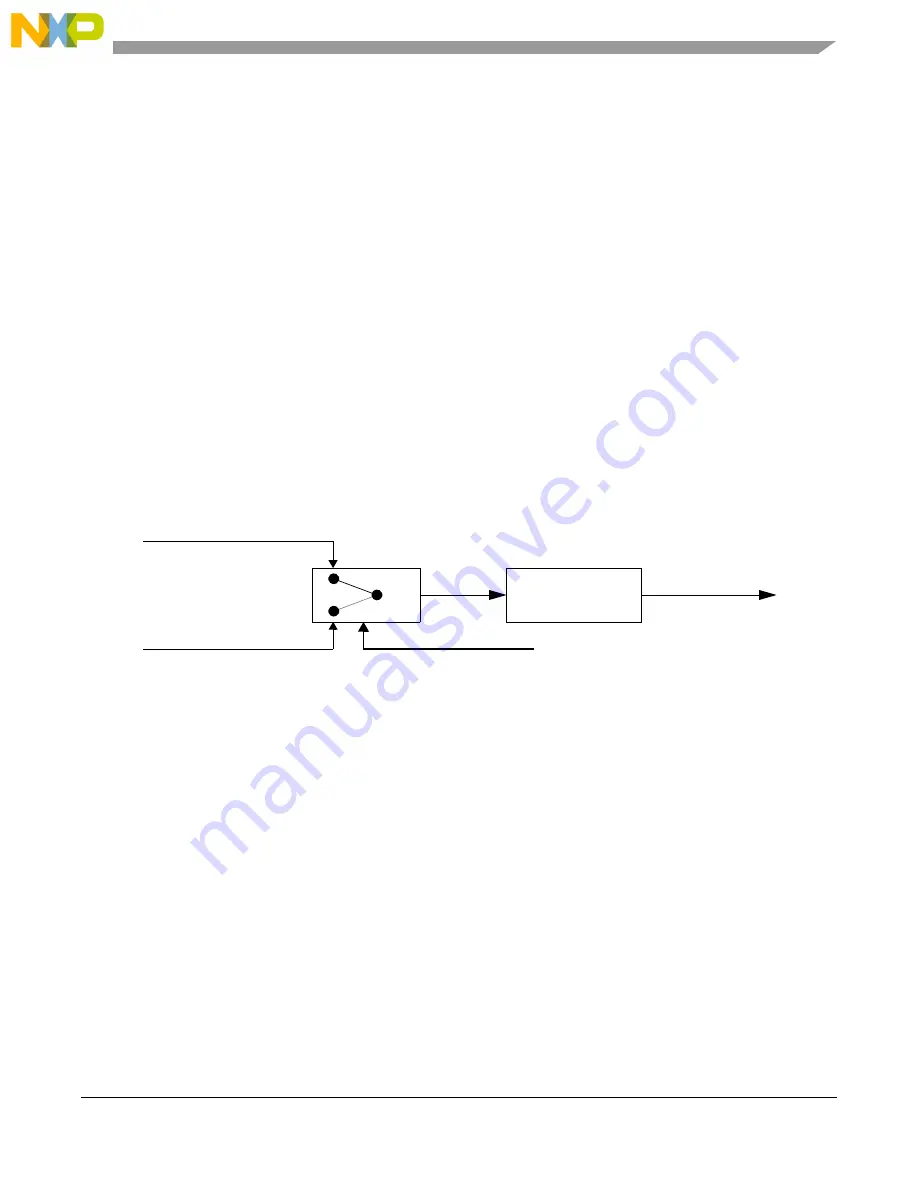
shows the structure of the clock generation circuitry that feeds the CAN Protocol Interface
(CPI) submodule. The clock source bit (CLKSRC) in the CR Register defines whether the internal clock
is connected to the output of a crystal oscillator (Oscillator Clock) or to the Peripheral Clock (generally
from a PLL). In order to guarantee reliable operation, the clock source should be selected while the module
is in Disable Mode (bit MDIS set in the Module Configuration Register).
Figure 32-18. CAN engine clocking scheme
The crystal oscillator clock should be selected whenever a tight tolerance (up to 0.1%) is required in the
CAN bus timing. The crystal oscillator clock has better jitter performance than PLL generated clocks.
The FlexCAN module supports a variety of means to setup bit timing parameters that are required by the
CAN protocol. The Control Register has various fields used to control bit timing parameters: PRESDIV,
PROPSEG, PSEG1, PSEG2 and RJW. See
Section 32.4.5.2, Control Register (CR)
.
The PRESDIV field controls a prescaler that generates the Serial Clock (Sclock), whose period defines the
‘time quantum’ used to compose the CAN waveform. A time quantum is the atomic unit of time handled
by the CAN engine.
A bit time is subdivided into three segments
1
):
1.
For further explanation of the underlying concepts please refer to ISO/DIS 11519
–
1, Section 10.3. Reference also the
Bosch CAN 2.0A/B protocol specification dated September 1991 for bit timing.
Peripheral Clock (PLL)
Oscillator Clock (Xtal)
CLKSRC
Prescaler
(1 .. 256)
Sclock
CPI Clock
f
Tq
f
CANCLK
Prescaler
V
alue
Þ
--------------------------------------------------------
=
Summary of Contents for MPC5644A
Page 2: ...MPC5644A Microcontroller Reference Manual Rev 6 2 Freescale Semiconductor...
Page 24: ...MPC5644A Microcontroller Reference Manual Rev 6 24 Freescale Semiconductor...
Page 26: ...MPC5644A Microcontroller Reference Manual Rev 6 26 Freescale Semiconductor...
Page 52: ...Introduction MPC5644A Microcontroller Reference Manual Rev 6 52 Freescale Semiconductor...
Page 56: ...Memory Map MPC5644A Microcontroller Reference Manual Rev 6 56 Freescale Semiconductor...
Page 1228: ...Decimation Filter MPC5644A Microcontroller Reference Manual Rev 6 1228 Freescale Semiconductor...
Page 1440: ...FlexCAN Module MPC5644A Microcontroller Reference Manual Rev 6 1440 Freescale Semiconductor...