


number of binary inputs are limited to seven, the coding functions are limited
to seven bits including the sign bit and thus the six bits are used in the coding
functions. The position limits for the tap positions at BCD, Gray and Natural binary
coding are ±39, ±63 and ±63 respectively.
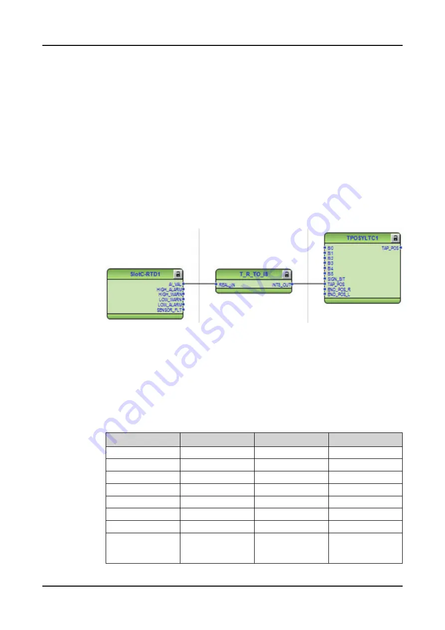
In this example, the transformer tap changer position indication is wired as a mA
signal from the corresponding measuring transducer. The position indication is
connected to input 1 (
AI_VAL1
) of the (RTD) module. The tap changer operating
range from the minimum to maximum turns of the tap and a corresponding mA
signal for the tap position are set in the RTD module. Since the values of the
RTD module outputs are floating point numbers, the float to integer (T_R_TO_I8)
conversion is needed before the tap position information can be fed to TPOSYLTC.
When there is a wired connection to the
TAP_POS
connector, the validated tap
changer position is presented in the
TAP_POS
output that is connected to other
functions, for example, OL5ATCC1. When there is no wired connection to the
TAP_POS
connector, the binary inputs are expected to be used for the tap changer
position information.
Figure 822: RTD/analog input configuration example
8.5.6
Signals
8.5.6.1
TPOSYLTC Input signals
Table 1450: TPOSYLTC Input signals
Name
Type
Default
Description
BI0
BOOLEAN
0=False
Binary input 1
BI1
BOOLEAN
0=False
Binary input 2
BI2
BOOLEAN
0=False
Binary input 3
BI3
BOOLEAN
0=False
Binary input 4
BI4
BOOLEAN
0=False
Binary input 5
BI5
BOOLEAN
0=False
Binary input 6
SIGN_BIT
BOOLEAN
0=False
Binary input sign bit
END_POS_R
BOOLEAN
0=False
End position raise or
highest allowed tap
position reached
Table continues on the next page
Measurement functions
1MRS759142 F
1502
REX640
Technical Manual
Содержание RELION REX640
Страница 1: ... RELION PROTECTION AND CONTROL REX640 Technical Manual ...
Страница 2: ......
Страница 3: ...Document ID 1MRS759142 Issued 2023 02 07 Revision F Copyright 2023 ABB All rights reserved ...
Страница 167: ...Figure 62 Signal outputs in power supply module 1MRS759142 F Basic functions REX640 Technical Manual 167 ...
Страница 184: ...Figure 84 mA channels working as mA outputs Basic functions 1MRS759142 F 184 REX640 Technical Manual ...
Страница 1868: ...Figure 989 ANSI extremely inverse time characteristics General function block features 1MRS759142 F 1868 REX640 Technical Manual ...
Страница 1869: ...Figure 990 ANSI very inverse time characteristics 1MRS759142 F General function block features REX640 Technical Manual 1869 ...
Страница 1870: ...Figure 991 ANSI normal inverse time characteristics General function block features 1MRS759142 F 1870 REX640 Technical Manual ...
Страница 1874: ...Figure 995 ANSI long time inverse time characteristics General function block features 1MRS759142 F 1874 REX640 Technical Manual ...
Страница 1875: ...Figure 996 IEC normal inverse time characteristics 1MRS759142 F General function block features REX640 Technical Manual 1875 ...
Страница 1876: ...Figure 997 IEC very inverse time characteristics General function block features 1MRS759142 F 1876 REX640 Technical Manual ...
Страница 1877: ...Figure 998 IEC inverse time characteristics 1MRS759142 F General function block features REX640 Technical Manual 1877 ...
Страница 1878: ...Figure 999 IEC extremely inverse time characteristics General function block features 1MRS759142 F 1878 REX640 Technical Manual ...
Страница 1882: ...Figure 1002 RI type inverse time characteristics General function block features 1MRS759142 F 1882 REX640 Technical Manual ...
Страница 1885: ...Figure 1004 UK rectifier inverse time characteristic 1MRS759142 F General function block features REX640 Technical Manual 1885 ...
Страница 1959: ......