RCTX
/ 1 to (2^14 - 1)
DLH + DLL
/ 16
48-MHz
clock
Shift reg (no
delays between
bytes on TX)
/ 1 to (2^8 - 1)
CFPS
/ 12
Pulse duty 1/3 or 1/4
or 5/12 or 1/2
DEMOD
16T
12CF
VOTE3
Data from TX
FIFO
Shift
Autostart
detect
16T
12CF
CIR transmitter
CIR receiver
Carrier frequency
prescaler
Data to RX FIFO
Manual or
automatic stop
CF: Carrier freq
uart-034
Public Version
UART/IrDA/CIR Functional Description
www.ti.com
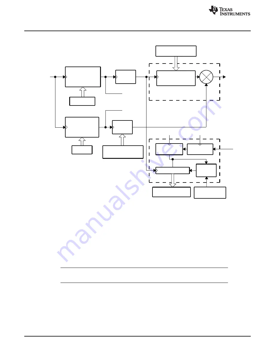
Figure 19-33. CIR Mode Block Components
Based on the requested modulation frequency, the UART3.
register must be set with the
correct dividing value to provide the more accurate pulse frequency:
Dividing value = (FCLK/12)/MODfreq
Where:
FCLK = System clock frequency (48 MHz)
12 = Real value of baud multiple
MODfreq = Effective frequency of the modulation (MHz)
Example: For a targeted modulation frequency of 36 kHz, the
value must be set to 111
(decimal), which provides a modulation frequency of 36.04 kHz.
NOTE:
The UART3.
register starts with a reset value of 105 (decimal), which translates
to a frequency of 38.1 kHz.
The duty cycle of these pulses is user-defined by the pulse duty register bits in the UART3.
configuration register.
shows the duty cycle.
2916
UART/IrDA/CIR
SWPU177N – December 2009 – Revised November 2010
Copyright © 2009–2010, Texas Instruments Incorporated


