


When both the MCR[RFEN] and MCR[DMA] bits are asserted (DMA feature for Rx
FIFO enabled), the function of the eight least significant interrupt flags (BUF7I–BUF0I)
are changed to support the DMA operation. BUF7I and BUF6I are not used, as well as
BUF4I–BUF1I. BUF5I indicates operating condition of FIFO, and BUF0I is used to
empty FIFO. Moreover, BUF5I does not generate a CPU interrupt, but generates a DMA
request. IMASK1 bits in Rx FIFO region are not considered when bit MCR[DMA] is
enabled. In addition the CPU must not clear the flag BUF5I when DMA is enabled.
Before enabling MCR[DMA], the CPU must service the IFLAGs asserted in the Rx FIFO
region. When MCR[DMA] is negated, the FIFO must be empty. FIFO must be disabled
when MCR[FDEN] is enabled.
Before updating MCR[MAXMB], CPU must service the IFLAG1 bits whose MB value
is greater than the MCR[MAXMB] to be updated; otherwise, they will remain set and be
inconsistent with the number of MBs available.
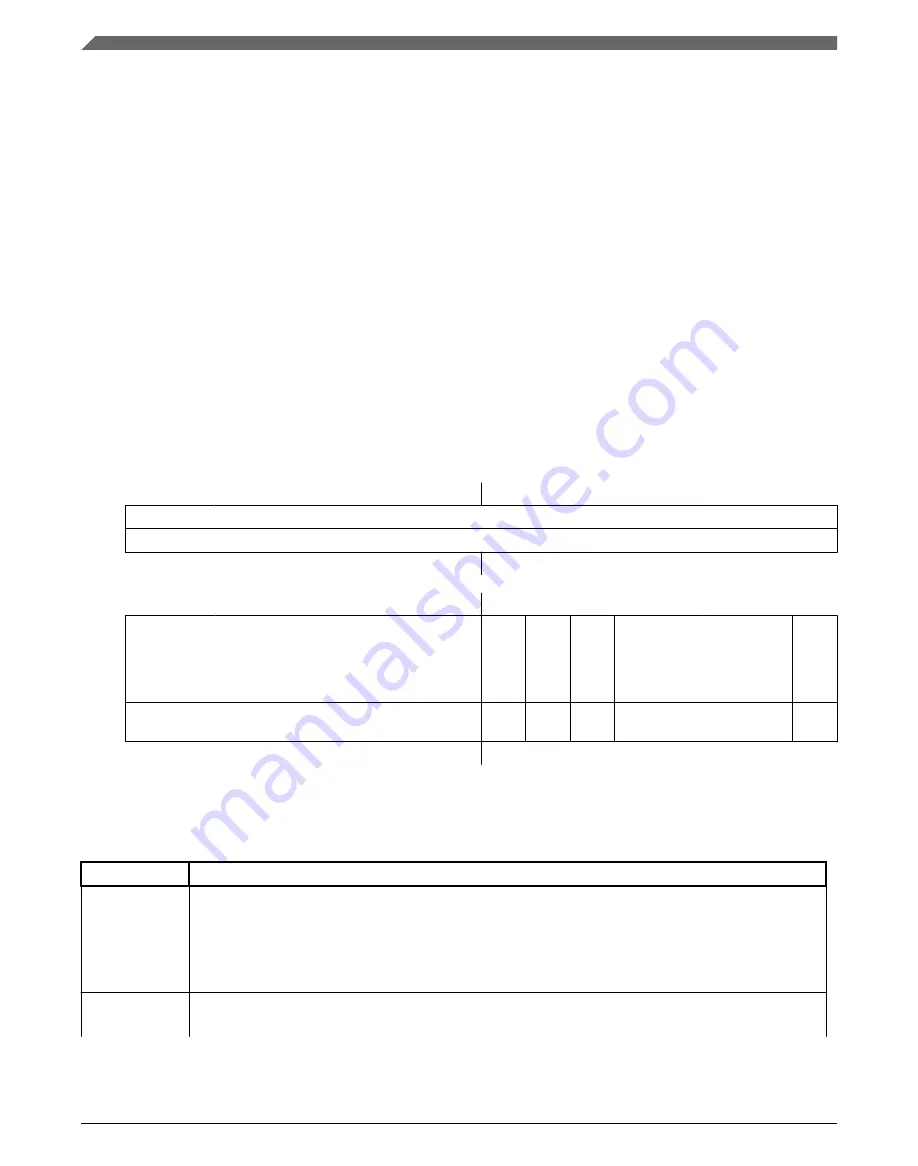
49.4.2.11.3 Diagram
Bits
31
30
29
28
27
26
25
24
23
22
21
20
19
18
17
16
R
W
W1C
Reset
0
0
0
0
0
0
0
0
0
0
0
0
0
0
0
0
Bits
15
14
13
12
11
10
9
8
7
6
5
4
3
2
1
0
R
W
W1C
W1C
W1C
W1C
W1C
W1C
Reset
0
0
0
0
0
0
0
0
0
0
0
0
0
0
0
0
49.4.2.11.4 Fields
Field
Function
31-8
BUF31TO8I
Buffer MBi Interrupt
Each bit flags the corresponding FlexCAN message buffer interrupt for MB31 to MB8.
0b - The corresponding buffer has no occurrence of successfully completed transmission or
reception.
1b - The corresponding buffer has successfully completed transmission or reception.
7
BUF7I
Buffer MB7 Interrupt Or Rx FIFO Overflow
When MCR[RFEN] is cleared (Rx FIFO disabled), this bit flags the interrupt for MB7.
Table continues on the next page...
Memory map/register definition
MWCT101xS Series Reference Manual, Rev. 3, 07/2019
1600
NXP Semiconductors
Summary of Contents for MWCT101 S Series
Page 2: ...MWCT101xS Series Reference Manual Rev 3 07 2019 2 NXP Semiconductors...
Page 42: ...MWCT101xS Series Reference Manual Rev 3 07 2019 42 NXP Semiconductors...
Page 50: ...Conventions MWCT101xS Series Reference Manual Rev 3 07 2019 50 NXP Semiconductors...
Page 70: ...Aliased bit band regions MWCT101xS Series Reference Manual Rev 3 07 2019 70 NXP Semiconductors...
Page 78: ...Pinout diagrams MWCT101xS Series Reference Manual Rev 3 07 2019 78 NXP Semiconductors...
Page 96: ...WCT101xS safety concept MWCT101xS Series Reference Manual Rev 3 07 2019 96 NXP Semiconductors...
Page 130: ...Functional description MWCT101xS Series Reference Manual Rev 3 07 2019 130 NXP Semiconductors...
Page 284: ...Functional description MWCT101xS Series Reference Manual Rev 3 07 2019 284 NXP Semiconductors...
Page 430: ...Functional Description MWCT101xS Series Reference Manual Rev 3 07 2019 430 NXP Semiconductors...
Page 472: ...Application Information MWCT101xS Series Reference Manual Rev 3 07 2019 472 NXP Semiconductors...
Page 528: ...Module clocks MWCT101xS Series Reference Manual Rev 3 07 2019 528 NXP Semiconductors...
Page 634: ...SRAM configuration MWCT101xS Series Reference Manual Rev 3 07 2019 634 NXP Semiconductors...
Page 818: ...Functional description MWCT101xS Series Reference Manual Rev 3 07 2019 818 NXP Semiconductors...
Page 960: ...Functional description MWCT101xS Series Reference Manual Rev 3 07 2019 960 NXP Semiconductors...
Page 992: ...ADC calibration scheme MWCT101xS Series Reference Manual Rev 3 07 2019 992 NXP Semiconductors...
Page 1348: ...Functional description MWCT101xS Series Reference Manual Rev 3 07 2019 1348 NXP Semiconductors...
Page 1366: ...Functional description MWCT101xS Series Reference Manual Rev 3 07 2019 1366 NXP Semiconductors...
Page 1514: ...Functional description MWCT101xS Series Reference Manual Rev 3 07 2019 1514 NXP Semiconductors...
Page 1726: ...Debug and security MWCT101xS Series Reference Manual Rev 3 07 2019 1726 NXP Semiconductors...
Page 1760: ...MWCT101xS Series Reference Manual Rev 3 07 2019 1760 NXP Semiconductors...


