


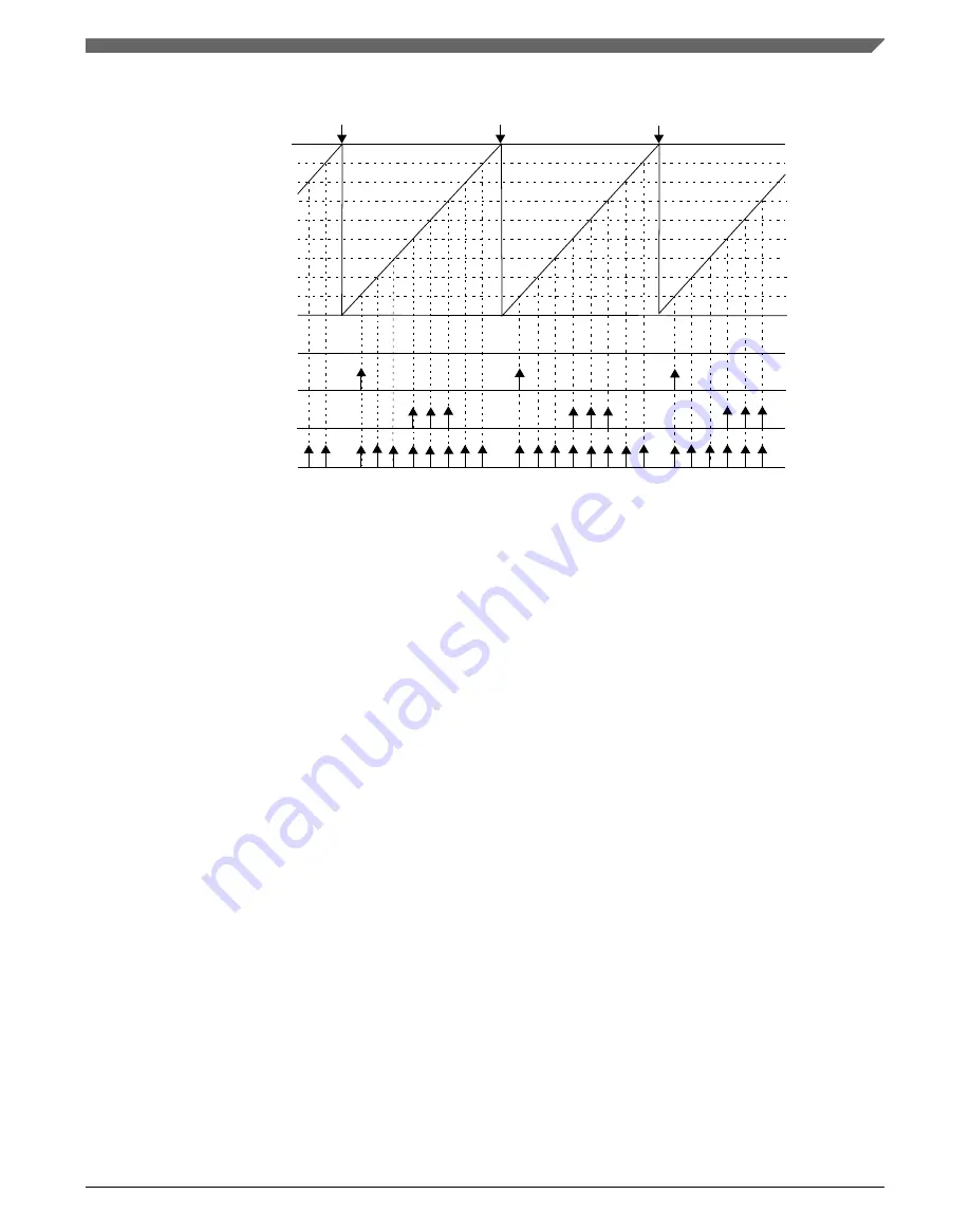
(a) CH0TRIG = 0, CH1TRIG = 0, CH2TRIG = 0, CH3TRIG = 0, CH4TRIG = 0, CH5TRIG = 0, CH6TRIG = 0, CH7TRIG = 0
(b) CH0TRIG = 1, CH1TRIG = 0, CH2TRIG = 0, CH3TRIG = 0, CH4TRIG = 0, CH5TRIG = 0, CH6TRIG = 0, CH7TRIG = 0
(c) CH0TRIG = 0, CH1TRIG = 0, CH2TRIG = 0, CH3TRIG = 1, CH4TRIG = 1, CH5TRIG = 1, CH6TRIG = 0, CH7TRIG = 0
(d) CH0TRIG = 1, CH1TRIG = 1, CH2TRIG = 1, CH3TRIG = 1, CH4TRIG = 1, CH5TRIG = 1, CH6TRIG = 1, CH7TRIG = 1
MOD
FTM counter = C5V
FTM counter = C4V
FTM counter = C3V
FTM counter = C2V
FTM counter = C1V
FTM counter = C0V
CNTIN
(a)
(b)
(c)
(d)
FTM counter = C6V
FTM counter = C7V
Note
the beginning of new PWM periods
Figure 41-87. External Trigger
41.5.23 Initialization Trigger
Initialization trigger allows FTM to generate a trigger in some specific points of FTM
counter cycle. This feature is controlled by the bits INITTRIGEN and ITRIGR. The
INITTRIGEN bit enables the initialization trigger generation and the ITRIGR bit selects
when the initialization trigger is generated.
If INITTRIGEN = 1 and ITRIGR = 1, then the initialization trigger is generated when
FTM counter reaches a reload point according to the frequency of the reload
opportunities (
).
NOTE
For this configuration of initilization trigger and in CPWM
mode, the bits CNTMAX and CNTMIN select where the
initialization trigger is generated.
If INITTRIGEN = 1 and ITRIGR = 0, then the initialization trigger is generated when
FTM counter is updated with the CNTIN register value. See the cases below.
1. When FTM counter is updated with CNTIN register value automatically.
Chapter 41 FlexTimer Module (FTM)
MWCT101xS Series Reference Manual, Rev. 3, 07/2019
NXP Semiconductors
1253
Summary of Contents for MWCT101 S Series
Page 2: ...MWCT101xS Series Reference Manual Rev 3 07 2019 2 NXP Semiconductors...
Page 42: ...MWCT101xS Series Reference Manual Rev 3 07 2019 42 NXP Semiconductors...
Page 50: ...Conventions MWCT101xS Series Reference Manual Rev 3 07 2019 50 NXP Semiconductors...
Page 70: ...Aliased bit band regions MWCT101xS Series Reference Manual Rev 3 07 2019 70 NXP Semiconductors...
Page 78: ...Pinout diagrams MWCT101xS Series Reference Manual Rev 3 07 2019 78 NXP Semiconductors...
Page 96: ...WCT101xS safety concept MWCT101xS Series Reference Manual Rev 3 07 2019 96 NXP Semiconductors...
Page 130: ...Functional description MWCT101xS Series Reference Manual Rev 3 07 2019 130 NXP Semiconductors...
Page 284: ...Functional description MWCT101xS Series Reference Manual Rev 3 07 2019 284 NXP Semiconductors...
Page 430: ...Functional Description MWCT101xS Series Reference Manual Rev 3 07 2019 430 NXP Semiconductors...
Page 472: ...Application Information MWCT101xS Series Reference Manual Rev 3 07 2019 472 NXP Semiconductors...
Page 528: ...Module clocks MWCT101xS Series Reference Manual Rev 3 07 2019 528 NXP Semiconductors...
Page 634: ...SRAM configuration MWCT101xS Series Reference Manual Rev 3 07 2019 634 NXP Semiconductors...
Page 818: ...Functional description MWCT101xS Series Reference Manual Rev 3 07 2019 818 NXP Semiconductors...
Page 960: ...Functional description MWCT101xS Series Reference Manual Rev 3 07 2019 960 NXP Semiconductors...
Page 992: ...ADC calibration scheme MWCT101xS Series Reference Manual Rev 3 07 2019 992 NXP Semiconductors...
Page 1348: ...Functional description MWCT101xS Series Reference Manual Rev 3 07 2019 1348 NXP Semiconductors...
Page 1366: ...Functional description MWCT101xS Series Reference Manual Rev 3 07 2019 1366 NXP Semiconductors...
Page 1514: ...Functional description MWCT101xS Series Reference Manual Rev 3 07 2019 1514 NXP Semiconductors...
Page 1726: ...Debug and security MWCT101xS Series Reference Manual Rev 3 07 2019 1726 NXP Semiconductors...
Page 1760: ...MWCT101xS Series Reference Manual Rev 3 07 2019 1760 NXP Semiconductors...


