


Frequency Modulated Phase-Locked Loop (FMPLL)
PXN20 Microcontroller Reference Manual, Rev. 1
7-16
Freescale Semiconductor
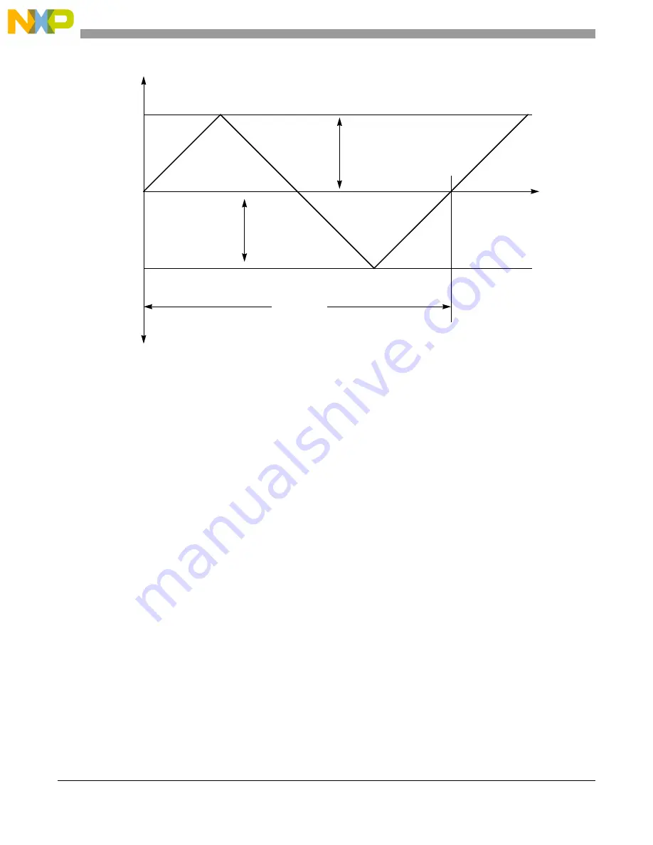
Figure 7-6. Frequency Modulation Waveform
7.4.3.4.1
Frequency Modulation Depth Calibration
The frequency modulation calibration system tunes a reference current into the modulation D/A so that the
modulation depth (F
max
and F
min
) remains within specification. Disable frequency modulation prior to
changing the EPREDIV, EMFD, or ERATE bit fields. Upon enabling frequency modulation a new
calibration sequence is performed. A change to EPREDIV, EMFD, or ERATE while modulation is active
invalidates calibration results.
This routine corrects for process variations, but because temperature can change after the calibration has
been performed, variation due to temperature drift is not eliminated. This system is also voltage dependent,
so if the supply changes after the sequence takes place, error incurred is not corrected. The calibration
system reuses the two counters in the lock detect circuit, the reference and feedback counters. The
reference counter remains clocked by the reference clock, but the feedback counter is clocked by the VCO
clock.
When the calibration routine is initiated by writing to the EDEPTH bits, the CALPASS and CALDONE
status bits are immediately cleared.
When calibration is induced the VCO is given time to settle before the feedback and reference counters
start counting. Full VCO clock cycles are counted by the feedback counter during this time to give the
initial center frequency count. When the reference counter has counted to the programmed number of
reference count cycles, the input to the feedback counter is disabled and the result is placed in the
COUNT0 register. The calibration system then enables modulation at programmed
Fm and the VCO gets
time to settle. Both counters are reset and restarted. The feedback counter begins to count full VCO clock
F
max
F
min
t
1
F
mod
----------------
=
t
f
F
max
= F
sys
+ {0.5%, 1%, 1.5%, 2%}
F
min
= F
sys
– {0.5%, 1%,1.5%, 2%}
F
mod
= F
extal
/Q where Q = {20, 40, 80}
Fm
Fm
Summary of Contents for PXN2020
Page 1: ...PXN20 Microcontroller Reference Manual Devices Supported PXN2020 PXN2120 PXN20RM Rev 1 06 2011...
Page 42: ...PXN20 Microcontroller Reference Manual Rev 1 lxiv Freescale Semiconductor...
Page 64: ...Introduction PXN20 Microcontroller Reference Manual Rev 1 1 22 Freescale Semiconductor...
Page 112: ...Signal Description PXN20 Microcontroller Reference Manual Rev 1 3 44 Freescale Semiconductor...
Page 118: ...Resets PXN20 Microcontroller Reference Manual Rev 1 4 6 Freescale Semiconductor...
Page 372: ...e200z6 Core Z6 PXN20 Microcontroller Reference Manual Rev 1 13 8 Freescale Semiconductor...
Page 412: ...e200z0 Core Z0 PXN20 Microcontroller Reference Manual Rev 1 14 14 Freescale Semiconductor...
Page 821: ...Media Local Bus MLB PXN20 Microcontroller Reference Manual Rev 1 Freescale Semiconductor 27 49...
Page 822: ...Media Local Bus MLB PXN20 Microcontroller Reference Manual Rev 1 27 50 Freescale Semiconductor...
Page 1376: ...Memory Map PXN20 Microcontroller Reference Manual Rev 1 A 118 Freescale Semiconductor...