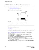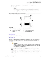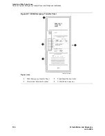
Install and Wire Telephones
Task List: Attendant Console Procedures
SI Installation and Upgrades
519
June 2004
Install the 26B1 Selector Console
Return to Task List
1
Connect the supplied 3-foot (0.9 m) D8AC cable to the modular jack on the bottom of the 26B1
Selector Console.
2
Route the cable to the attendant console and connect to the DXS/BLF jack.
3
Attach labels according to the Attendant Console form.
4
Administer the console using Administrator’s Guide for Avaya Communication Manager (555-
233-506).
Return to Task List
Connect External Alarm Indicators and Auxiliary Power
Return to Task List
Alarms can be generated on adjunct equipment, sent to the DEFINITY System, and recorded and
reported as “external alarms.” A typical major alarm input is from an Uninterruptible Power Supply
(UPS).
The system provides a relay contact that can operate a customer-provided alarm, such as a light or bell.
The circuitry and power source are customer- provided. The alarm device must not exceed a rating of
more than 100 Volts at 0.75 Amp.
1
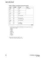
Connect 1 major and 1 minor alarm input pair to the trunk/auxiliary field from the AUX
connector. See
Table 24, Alarm Inputs at AUX Connector,
on page 519.
2
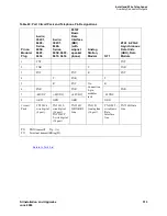
Connect an external alarm output through pins 48 and 23 of the AUX connector. See
Table 25,
Alarm Output at AUX Connector,
on page 520.
3
Note which device connects to which alarm and give this information to your Avaya
representative for troubleshooting purposes.
4
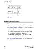
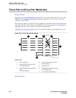
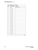
Connect emergency transfer power and auxiliary power as shown in
Table 26, Emergency
Transfer and Auxiliary Power,
on page 520. Auxiliary power includes power to an attendant
console or adjunct device.
Table 24: Alarm Inputs at AUX Connector
Color
AUX Connector
White-Blue
AP1 (Pin 26) Major Alarm Input
Blue-White
Ground (Pin 1)
White-Orange
AP2 (Pin 27) Minor Alarm Input
Orange-White
Ground (Pin 2)
Содержание MCC1
Страница 38: ...Upgrades to Avaya Commnication Manager Made Easy Before you start 38 SI Installation and Upgrades June 2004 ...
Страница 326: ...Installation for MCC1 Multicarrier Cabinets Made Easy 326 SI Installation and Upgrades June 2004 ...
Страница 362: ... Single Carrier Cabinets Made Easy 362 SI Installation and Upgrades June 2004 ...
Страница 498: ...Test the System LED Indicators 498 SI Installation and Upgrades June 2004 ...
Страница 650: ...Add IP Solutions Task list Upgrade a TN802 to a TN802B 650 SI Installation and Upgrades June 2004 ...
Страница 692: ...Install and Administer Trunks Add TN1654 DS1 Converter r only 692 SI Installation and Upgrades June 2004 ...
Страница 770: ...Connecting and Handling Fiber Optic Cables Cleaning Fiber Optic Cables 770 SI Installation and Upgrades June 2004 ...
Страница 784: ...Connector and Cable Diagrams Pinout Charts DS1 Interface Cable H600 307 784 SI Installation and Upgrades June 2004 ...
Страница 792: ...UPS Installation for SCC1 EPN A Carrier Cabinet Task List Install UPS 792 SI Installation and Upgrades June 2004 ...
Страница 874: ...Index Z 874 SI Installation and Upgrades June 2004 ...


