Adjuncts and Peripherals
DS1/T1 CPE loopback jack
SI Installation and Upgrades
817
June 2004
With a smart jack
Install the loopback jack at the interface to the smart jack, if possible. This position provides maximum
coverage of CPE wiring when remote loopback tests are run.
If the smart jack is not accessible, install the loopback jack at the extended demarcation point.
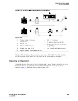
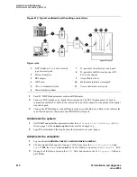
If there is no extended demarcation point, install the loopback jack directly at the network interface point
as shown in
Figure 315
.
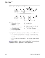
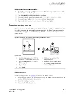
If there is an extended demarcation point and the smart jack is not accessible, install the loopback jack as
shown in
Figure 316
.
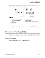
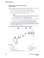
If there is an extended demarcation point, but the smart jack is accessible, install the loopback jack as
shown in .
1
To install the loopback jack, simply disconnect the RJ-48 (8-wide) connector at the appropriate
interface point and connect the loopback jack in series with the DS1 span. See
Figure 315
through
Figure 319
.
2
Plug the H600-383 cable from the ICSU into the female connector on the loopback jack.
3
Plug the male connector on the loopback jack cable into the network interface point.
NOTE:
Do not remove the loopback jack after installation. This is not a test tool and should
always be available to remotely test a DS1 span.
Without a smart jack
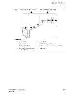
Install the loopback jack at the point where the cabling from the ICSU plugs into the dumb block. If there
is more than one dumb block, choose the one that is closest to the Interface Termination feed or the fiber
MUX to provide maximum coverage for loopback jack tests. Refer to
Figure 318
and
Figure 319
.
1
To install the loopback jack, simply disconnect the RJ-48 (8-wide) connector at the appropriate
interface point and connect the loopback jack in series with the DS1 span. See
Figure 315
through
Figure 319
.
2
Plug the H600-383 cable from the ICSU, or from the MM710, into the female connector on the
loopback jack.
3
Plug the male connector on the loopback jack cable into the network interface point.
NOTE:
Do not remove the loopback jack after installation. This is not a test tool and should
always be available to remotely test a DS1 span.
Содержание MCC1
Страница 38: ...Upgrades to Avaya Commnication Manager Made Easy Before you start 38 SI Installation and Upgrades June 2004 ...
Страница 326: ...Installation for MCC1 Multicarrier Cabinets Made Easy 326 SI Installation and Upgrades June 2004 ...
Страница 362: ... Single Carrier Cabinets Made Easy 362 SI Installation and Upgrades June 2004 ...
Страница 498: ...Test the System LED Indicators 498 SI Installation and Upgrades June 2004 ...
Страница 650: ...Add IP Solutions Task list Upgrade a TN802 to a TN802B 650 SI Installation and Upgrades June 2004 ...
Страница 692: ...Install and Administer Trunks Add TN1654 DS1 Converter r only 692 SI Installation and Upgrades June 2004 ...
Страница 770: ...Connecting and Handling Fiber Optic Cables Cleaning Fiber Optic Cables 770 SI Installation and Upgrades June 2004 ...
Страница 784: ...Connector and Cable Diagrams Pinout Charts DS1 Interface Cable H600 307 784 SI Installation and Upgrades June 2004 ...
Страница 792: ...UPS Installation for SCC1 EPN A Carrier Cabinet Task List Install UPS 792 SI Installation and Upgrades June 2004 ...
Страница 874: ...Index Z 874 SI Installation and Upgrades June 2004 ...

