R5/R6/R7/R8si to Avaya Communication Manager
Task List: R5/R6/R7/R8si to Avaya Communication Manager
SI Installation and Upgrades
123
June 2004
6
Type
change cabinet 1
and press Enter.
In the
Carrier Type
column change the “B” carrier to processor and submit the form.
7
Type
change system-parameters duplication
and press Enter.
Set the
Enable Operation of SPE Duplication
field to y and submit the form.
8
Type
save translation
and press Enter.
After the translations have been copied (about 10 minutes), the system returns an error code,
which must be a zero; otherwise, the translations are not copied.
9
Type
reset system 3
preserve-license
(or
reset system 3
no-preserve-license
, since the
License File has been saved in translations) and press Enter.
New simplex and upgraded G3r only
1
Type
save translation
and press Enter.
After the translations have been copied (about 10 minutes), the system returns an error code,
which must be a zero; otherwise, the translations are not copied.
2
Type
reset system 3
and press Enter.
Wait until the system has completely reset before continuing.
3
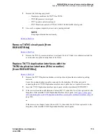
If the system has IP endpoints registered, unplug the Ethernet cable from the TN799 (C-LAN)
circuit pack.
This disconnects (unregisters) all IP endpoints.
4
Type
set time
and press Enter.
Ensure that the system date and time are set correctly.
5
Use one of these installation methods:
—
Direct connection between the switch and RFA
—
No connection between the switch and RFA
New or upgraded G3si only
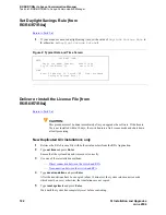
1
Retrieve the RFA License File with both serial numbers from the RFA Application.
2
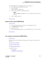
If the system has IP endpoints registered, unplug the Ethernet cable from the TN799 (C-LAN)
circuit pack.
This disconnects (unregisters) all IP endpoints.
3
Type
set time
and press Enter.
Ensure that the system date and time are set correctly.
4
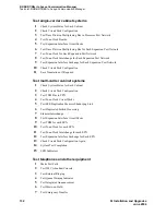
For duplicated systems only type
status system all
and press Enter.
Ensure that the standby SPE is not in the maintenance state. If it is, wait for the maintenance state
to finish.
5
Use one of these installation methods:
—
Direct connection between the switch and RFA
—
No connection between the switch and RFA
Содержание MCC1
Страница 38: ...Upgrades to Avaya Commnication Manager Made Easy Before you start 38 SI Installation and Upgrades June 2004 ...
Страница 326: ...Installation for MCC1 Multicarrier Cabinets Made Easy 326 SI Installation and Upgrades June 2004 ...
Страница 362: ... Single Carrier Cabinets Made Easy 362 SI Installation and Upgrades June 2004 ...
Страница 498: ...Test the System LED Indicators 498 SI Installation and Upgrades June 2004 ...
Страница 650: ...Add IP Solutions Task list Upgrade a TN802 to a TN802B 650 SI Installation and Upgrades June 2004 ...
Страница 692: ...Install and Administer Trunks Add TN1654 DS1 Converter r only 692 SI Installation and Upgrades June 2004 ...
Страница 770: ...Connecting and Handling Fiber Optic Cables Cleaning Fiber Optic Cables 770 SI Installation and Upgrades June 2004 ...
Страница 784: ...Connector and Cable Diagrams Pinout Charts DS1 Interface Cable H600 307 784 SI Installation and Upgrades June 2004 ...
Страница 792: ...UPS Installation for SCC1 EPN A Carrier Cabinet Task List Install UPS 792 SI Installation and Upgrades June 2004 ...
Страница 874: ...Index Z 874 SI Installation and Upgrades June 2004 ...


