System 75 Small-Cabinet to R8si (Blowback)
Task List: System 75 Small Cabinet to R8si
SI Installation and Upgrades
321
June 2004
Insert An Isolator
Power-Failure Stations
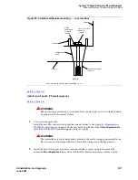
During routine switch operation, the ground for the power-failure stations is derived from the system’s
auxiliary cable. This ground will be disconnected during the upgrade, thus disabling the power-failure
stations. Therefore, a ground strap will have to be run to the power-failure transfer panel. This strap
should be connected shortly after power is removed and then disconnected just before power is restored
to the upgraded system.
To minimize downtime during the R8si upgrade, power-failure transfer equipment should be tested and,
if need be, repaired before the hardware upgrade begins.
Upgrade overview: System 75 XE
When you upgrade a System 75 XE, consider the following:
•
Many configurations of System 75 XEs are in the field.
•
Each system can have a unique hardware and software configuration.
•
How you upgrade a system depends on its present configuration.
•
To upgrade a System 75 XE, you replace the control cabinet with either:
— An R7si/R8si enhanced control cabinet for a PPN upgrade
— An expansion control cabinet for an EPN upgrade
•
For an upgrade to a duplicated R7si or R8si PPN, you also add an enhanced duplicated control
cabinet.
Relocating PPN port circuit packs
When you upgrade a System 75 XE:
•
You can need to move and manually retranslate port circuit packs from the control cabinet.
•
You replace the System 75 XE control cabinet with 14 port slots with an R7si/R8si enhanced
control cabinet with 16 port slots. This provides 2 extra port slots.
•
However, out of these 16 port slots, nonport-related (control and service) circuit packs may need
to occupy certain slots:
— If you are replacing the TN756 tone detector/generator in the System 75 XE control
cabinet, use a new TN2182 tone-clock. The TN2182 replaces the tone-detector circuits on
the TN756.
— If you simultaneously add an EPN, you must install a TN776 or TN570D expansion
interface circuit pack in slot 1 of the new R7si enhanced control cabinet.
— If the control cabinet in the System 75 XE holds a TN755B power supply in slot 13 or 14,
this circuit pack is relocated to port slots 15 or 16 of the new R7si/R8si enhanced control
cabinet (with no effect on available port circuits).
•
If you have all of the above scenarios, the result is neither a gain nor a loss of port slots.
Содержание MCC1
Страница 38: ...Upgrades to Avaya Commnication Manager Made Easy Before you start 38 SI Installation and Upgrades June 2004 ...
Страница 326: ...Installation for MCC1 Multicarrier Cabinets Made Easy 326 SI Installation and Upgrades June 2004 ...
Страница 362: ... Single Carrier Cabinets Made Easy 362 SI Installation and Upgrades June 2004 ...
Страница 498: ...Test the System LED Indicators 498 SI Installation and Upgrades June 2004 ...
Страница 650: ...Add IP Solutions Task list Upgrade a TN802 to a TN802B 650 SI Installation and Upgrades June 2004 ...
Страница 692: ...Install and Administer Trunks Add TN1654 DS1 Converter r only 692 SI Installation and Upgrades June 2004 ...
Страница 770: ...Connecting and Handling Fiber Optic Cables Cleaning Fiber Optic Cables 770 SI Installation and Upgrades June 2004 ...
Страница 784: ...Connector and Cable Diagrams Pinout Charts DS1 Interface Cable H600 307 784 SI Installation and Upgrades June 2004 ...
Страница 792: ...UPS Installation for SCC1 EPN A Carrier Cabinet Task List Install UPS 792 SI Installation and Upgrades June 2004 ...
Страница 874: ...Index Z 874 SI Installation and Upgrades June 2004 ...

