Install and Wire Telephone Power Supply
1145B Power Supply
550
SI Installation and Upgrades
June 2004
Perform these tasks in order:
1
Install the Wall-Mounting Plates
on page 554
2
Mount the 1146B Power Distribution Unit
on page 555
3
Install the Battery Mounting/Wiring
on page 557
4
Install the Expanded Power Distribution Unit
on page 557
5
Power Up and Test the Power Supply
on page 559
6
Wire the 1146B Power Distribution Unit
on page 559
7
Reset LEDs on Power Distribution Unit
on page 560
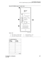
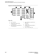
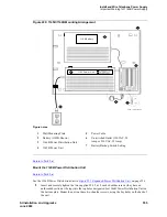
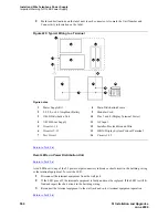
Figure 218, 1145B/1146B Mounting Arrangement,
on page 551 shows how the standard power supply
and wall-mounting plates fit together.
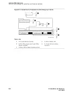
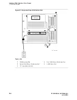
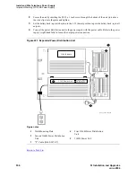
Figure 219, Expanded Power Distribution Unit,
on page 552 shows
the expanded power supply components (power distribution unit and “T” cable).
A manual switch on the distribution unit allows the user to redirect reserve power to outputs 1 through 32
so all outputs are provided battery reserve power, or to outputs 1 through 8 to provide high power above
6.25 watts.
NOTE:
The switch must be set to the 1-32 position.
The 1145B/1146B is a -48V power supply with 275 watts total output. Each output circuit is current
limited by a Polymer Positive Temperature Coefficient Resistance Device (PTC) that limits the maximum
output to 12 watts. Each 1146B output has an LED to indicate the status of the PTC. If the LED is on, the
PTC has a short on that power pair.
Not all outputs can simultaneously provide 12 watts. The average power per output cannot exceed 8.6
watts (275/32 = 8.6). The 1145B is designed to power one ISDN terminal or DCP adjunct per output. The
maximum number of terminals or adjuncts is 32 at less than or equal to 6.25 watts each. The 1145B is
required for installations outside the United States.
Auxiliary power (local or bulk) is always required for the following:
•
Attendant Console 302C1
•
Any 8520 terminal
•
Any 7500- or 8500-series terminal with an asynchronous data module
•
Any 7500-series terminal whether in passive bus, or point to point (one per BRI port)
•
Any 8510 terminal in passive bus or with an asynchronous data module (unless the 8510 will not
be used to support data or video)
•
PassageWay adapter interface
•
Some 8400-series terminal and adjuncts
•
Some 7400-series terminal and adjuncts
Содержание MCC1
Страница 38: ...Upgrades to Avaya Commnication Manager Made Easy Before you start 38 SI Installation and Upgrades June 2004 ...
Страница 326: ...Installation for MCC1 Multicarrier Cabinets Made Easy 326 SI Installation and Upgrades June 2004 ...
Страница 362: ... Single Carrier Cabinets Made Easy 362 SI Installation and Upgrades June 2004 ...
Страница 498: ...Test the System LED Indicators 498 SI Installation and Upgrades June 2004 ...
Страница 650: ...Add IP Solutions Task list Upgrade a TN802 to a TN802B 650 SI Installation and Upgrades June 2004 ...
Страница 692: ...Install and Administer Trunks Add TN1654 DS1 Converter r only 692 SI Installation and Upgrades June 2004 ...
Страница 770: ...Connecting and Handling Fiber Optic Cables Cleaning Fiber Optic Cables 770 SI Installation and Upgrades June 2004 ...
Страница 784: ...Connector and Cable Diagrams Pinout Charts DS1 Interface Cable H600 307 784 SI Installation and Upgrades June 2004 ...
Страница 792: ...UPS Installation for SCC1 EPN A Carrier Cabinet Task List Install UPS 792 SI Installation and Upgrades June 2004 ...
Страница 874: ...Index Z 874 SI Installation and Upgrades June 2004 ...

