System 75 Small-Cabinet to R8si (Blowback)
Task List: System 75 Small Cabinet to R8si
SI Installation and Upgrades
305
June 2004
Install new control cabinet [75 small upgrade]
Return to Task List
NOTE:
This procedure is for systems not requiring earthquake protection.
The new control cabinet already contains a TN790B circuit pack, and the network control and packet
control mechanism are already in place.
!
DANGER
:
The cabinet may weigh as much as 130 pounds and requires 2 handlers. Use caution
to avoid injury.
1
Roll the multi-carrier cabinet into position at the desired location.
2
Install hole plugs (provided with cabinet) in the holes previously occupied by the two carriage
bolts at the bottom rear of the cabinet.
Return to Task List
Install new control cabinet with earthquake protection [75 small upgrade]
Return to Task List
NOTE:
This procedure is for systems requiring earthquake protection.
The new control cabinet already contains a TN790B circuit pack, and the network control and packet
control mechanism are already in place.
!
DANGER
:
The cabinet may weigh as much as 130 pounds and requires 2 handlers. Use caution
to avoid injury.
1
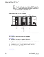
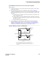
Roll the multi-carrier cabinet into position at the desired location.
2
Place the front mounting angle at the location selected for the front of the control cabinet.
3
Using the angle as a template, mark the locations of the 2 mounting bolts.
4
Drill 2 holes 1/2 inch in diameter and 1-1/2 inches deep at the spots marked in
Step 3
.
5
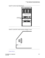
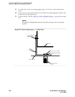
Mount the front mounting angle to the floor (
Figure 79, Front mounting angle — concrete floor,
on page 306).
6
Move the cabinet back into place, and temporarily stabilize the cabinet by attaching the cabinet to
the angle with 2 No. 12-24 by 1/2-inch thread-forming screws.
7
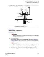
Insert a pencil or marker through the 2 holes (previously occupied with carriage bolts) in the
bottom rear of the cabinet, and mark the floor directly beneath each hole.
8
Remove the 2 screws installed in
Step 6
, and move the cabinet out of the way.
9
Drill 2 holes 1/2 inch in diameter and 1-1/2 inches deep at the spots marked in
Step 7
.
10
Move the cabinet back into place.
Содержание MCC1
Страница 38: ...Upgrades to Avaya Commnication Manager Made Easy Before you start 38 SI Installation and Upgrades June 2004 ...
Страница 326: ...Installation for MCC1 Multicarrier Cabinets Made Easy 326 SI Installation and Upgrades June 2004 ...
Страница 362: ... Single Carrier Cabinets Made Easy 362 SI Installation and Upgrades June 2004 ...
Страница 498: ...Test the System LED Indicators 498 SI Installation and Upgrades June 2004 ...
Страница 650: ...Add IP Solutions Task list Upgrade a TN802 to a TN802B 650 SI Installation and Upgrades June 2004 ...
Страница 692: ...Install and Administer Trunks Add TN1654 DS1 Converter r only 692 SI Installation and Upgrades June 2004 ...
Страница 770: ...Connecting and Handling Fiber Optic Cables Cleaning Fiber Optic Cables 770 SI Installation and Upgrades June 2004 ...
Страница 784: ...Connector and Cable Diagrams Pinout Charts DS1 Interface Cable H600 307 784 SI Installation and Upgrades June 2004 ...
Страница 792: ...UPS Installation for SCC1 EPN A Carrier Cabinet Task List Install UPS 792 SI Installation and Upgrades June 2004 ...
Страница 874: ...Index Z 874 SI Installation and Upgrades June 2004 ...


