Install Telecommunications Cabling
Station Wiring Design
SI Installation and Upgrades
417
June 2004
Station Wiring Design
The following hardware and cabling is used:
•
Information Outlets
on page 417 (modular wall jacks)
•
Station Cables
on page 417
•
Closets
on page 418
— Site locations
— Satellite locations
A brief description of each of the above listed items follows. Ordering information is not provided for
station cables and information outlets.
Information Outlets
Information outlets are 8-pin modular wall jacks. Most of the outlets are wired with push-on connections.
Information outlets are also available that connect to a double modular plug-ended 4-pair station cable
routed from the MDF, a site/satellite location, or an adapter.
Station Cables
For clarity, a station cable is either a 25-pair cable, multiple 25-pair cable, or 4-pair D-inside wire (DIW)
run from the equipment room, site/satellite location, or adapter to the information outlets. The following
station cables are available. See
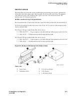
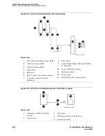
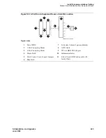
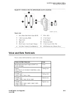
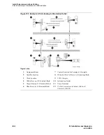
Figure 144, Example of Extending 4-Pair Station Cables,
on page 419.
25-pair station cable
—
Use between the equipment room and site/ satellite locations or adapters. Use an
A25D cable (male to male) between the equipment room and satellite closet. Use a B25A cable between
the equipment room and site closet or adapter.
Multiple 25-pair station cable
—
Use between the equipment room and site/satellite locations or
adapters. This cable consists of individually sheathed 25-pair cables with a factory-installed 25-pair
connector on each end. Use a male to female cable to connect between the equipment room and site
location or adapter. Use a male to male cable to connect between the equipment room and satellite
location. Staggered-finger cables are recommended for all multiple 25-pair station cables and are
available in both double-ended and single-ended types.
Single modular plug-ended 4-pair station cable
—
Use this cable between adapters and information
outlets that require push-on connections. It can also be used when 4-pair station cables are field-
terminated on the 110-type terminal blocks in the equipment room or satellite closet and modularly
connected to information outlets. The station cables are available in the following lengths:
•
10 ft (3.05 m)
•
25 ft (7.62 m)
•
50 ft (15.24 m)
•
75 ft (22.86 m)
•
100 ft (30.5 m)
Содержание MCC1
Страница 38: ...Upgrades to Avaya Commnication Manager Made Easy Before you start 38 SI Installation and Upgrades June 2004 ...
Страница 326: ...Installation for MCC1 Multicarrier Cabinets Made Easy 326 SI Installation and Upgrades June 2004 ...
Страница 362: ... Single Carrier Cabinets Made Easy 362 SI Installation and Upgrades June 2004 ...
Страница 498: ...Test the System LED Indicators 498 SI Installation and Upgrades June 2004 ...
Страница 650: ...Add IP Solutions Task list Upgrade a TN802 to a TN802B 650 SI Installation and Upgrades June 2004 ...
Страница 692: ...Install and Administer Trunks Add TN1654 DS1 Converter r only 692 SI Installation and Upgrades June 2004 ...
Страница 770: ...Connecting and Handling Fiber Optic Cables Cleaning Fiber Optic Cables 770 SI Installation and Upgrades June 2004 ...
Страница 784: ...Connector and Cable Diagrams Pinout Charts DS1 Interface Cable H600 307 784 SI Installation and Upgrades June 2004 ...
Страница 792: ...UPS Installation for SCC1 EPN A Carrier Cabinet Task List Install UPS 792 SI Installation and Upgrades June 2004 ...
Страница 874: ...Index Z 874 SI Installation and Upgrades June 2004 ...

