Install Fiber Optic Cable Pass-Thru Kit for SCC1 (Single-Carrier) Cabinets
DS1C Converter Complex Administration for TN574 Circuit Packs
SI Installation and Upgrades
215
June 2004
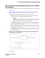
•
DS1CONV Board Location
—
Enter the cabinet, carrier, and slot that identifies the physical
location of the converter circuit pack connected to the first endpoint of the fiber link. This is
entered on Page 1 and displays on Page 2.
•
DS1CONV Board Type
—
Display-only field showing the type of DS1 Converter circuit pack
for the first endpoint.
•
DS1CONV Board Location
—
Enter the cabinet, carrier, and slot that identifies the physical
location of the converter circuit pack connected to the second endpoint of the fiber link.
•
DS1CONV Board Type
—
Display-only field showing the type of DS1 Converter circuit pack
for the second endpoint. This field is updated via the Change Circuit-packs command.
•
Facility Installed
—
Enter yes in the B, C, and D columns under the DS1 Converter Facilities
heading to indicate that this DS1 facility is physically installed. At least facility A must be
installed within the converter complex. Default is yes for Facility A.
•
Passes Far-end Clock
—
Enter yes in the B, C, and D columns under the DS1 Converter
Facilities heading to indicate that this DS1 facility is suitable to be used as a clock source. If the
DS1 signal does not come directly from the far end converter circuit pack or the network (such as
when the signal is converted from digital to analog and then back to digital), enter no. Default is
yes for Facility A.
This field determines whether the DS1 converter circuit pack can use receive DS1 signal timing to
time the transmit fiber signal. This is necessary for passing timing from a master PN to a slave PN
across a Converter Complex.
•
Digital Data Compatible
—
Enter yes (default) in the B, C, and D columns under the DS1
Converter Facilities heading to indicate that this DS1 facility is suitable for transmission of digital
data. At least Facility A must be suitable for transmission of digital data. If Customer Premises
Equipment that alters digital data exists on this facility (such as with a channel expansion
multiplexer), enter no.
•
Line Coding
—
Enter the line coding format, ami-zcs (default), or ami-basic, b8zs, or hdb3 in
the A, B, C, and D columns under the DS1 Converter Facilities heading for each DS1 facility.
When ami-zcs line coding is used, all-zero bytes are prevented from being transmitted on the DS1
facility because a 1 is arbitrarily written into the second position of each byte. Thus, if no
measures are taken to prevent it, ami-zcs line coding results in data corruption. The DS1CONV
circuit pack protects the packet facility (one of up to four facilities dynamically allocated by the
DS1CONV circuit pack) from corruption through a special escape mechanism.
When b8zs line coding is used, it maintains DS1 facility’s ones-density requirements by encoding
a zero data byte into a specific unique pattern of bipolar violations on the DS1 line. The opposite
end recognizes this pattern and replaces it with a zero data byte when the data is recovered at the
receiving end.
NOTE:
Note that although the esf framing mode and b8zs line coding are the preferable modes of
operation, you should confirm that the DS1 facilities support them before selecting this
line coding.
•
Framing Mode
—
Enter the framing format, esf (default) or d4, in the A, B, C, and D columns
under the DS1 Converter Facilities heading for each DS1 facility.
NOTE:
The D4 format is supported by the Converter circuit packs, but because of problems
inherent with this format (specifically, inability to frame on a bit stream that contains data
that emulates the D4 framing pattern), its use is discouraged.
Содержание MCC1
Страница 38: ...Upgrades to Avaya Commnication Manager Made Easy Before you start 38 SI Installation and Upgrades June 2004 ...
Страница 326: ...Installation for MCC1 Multicarrier Cabinets Made Easy 326 SI Installation and Upgrades June 2004 ...
Страница 362: ... Single Carrier Cabinets Made Easy 362 SI Installation and Upgrades June 2004 ...
Страница 498: ...Test the System LED Indicators 498 SI Installation and Upgrades June 2004 ...
Страница 650: ...Add IP Solutions Task list Upgrade a TN802 to a TN802B 650 SI Installation and Upgrades June 2004 ...
Страница 692: ...Install and Administer Trunks Add TN1654 DS1 Converter r only 692 SI Installation and Upgrades June 2004 ...
Страница 770: ...Connecting and Handling Fiber Optic Cables Cleaning Fiber Optic Cables 770 SI Installation and Upgrades June 2004 ...
Страница 784: ...Connector and Cable Diagrams Pinout Charts DS1 Interface Cable H600 307 784 SI Installation and Upgrades June 2004 ...
Страница 792: ...UPS Installation for SCC1 EPN A Carrier Cabinet Task List Install UPS 792 SI Installation and Upgrades June 2004 ...
Страница 874: ...Index Z 874 SI Installation and Upgrades June 2004 ...


