


VNA GUI Reference
R&S
®
ZNL/ZNLE
390
User Manual 1178.5966.02 ─ 07
9.9.1
Diagram Tab
Selects a diagram as the active diagram, defines a title, deletes or adds diagrams and
arranges them on the screen. Many of the functions are unavailable if the active chan-
nel setup contains only one diagram.
Active Diagram
Selects the active diagram.
Each channel setup screen can display several diagrams simultaneously, each with a
variable number of traces. One of these diagrams and traces is active at each time.
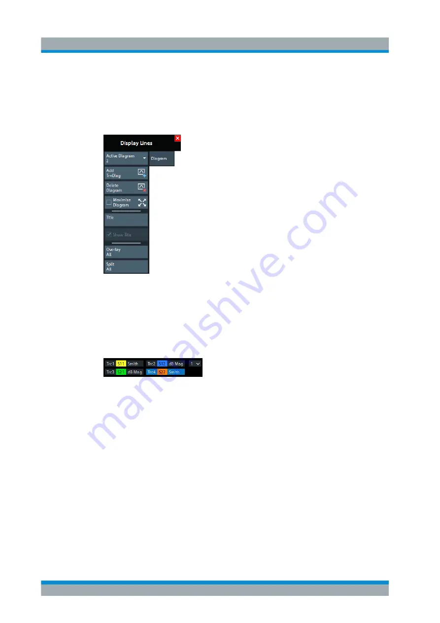
The diagram number (or name) in the upper right corner of the active diagram is high-
lighted. At the same time, the active trace is highlighted in the trace list on top of the
active diagram (Trc3 in the figure below):
The analyzer provides several tools for activating diagrams:
●
tap on a point in the diagram to activate the diagram including the last active trace
in the diagram.
●
tap on a trace list to activate the trace including the corresponding diagram.
●
activate a particular trace including the
corresponding diagram.
Remote command:
DISPlay[:WINDow<Wnd>]:TRACe<WndTr>:CATalog?
Add Trace + Diagram
Creates a diagram and a trace which is displayed in the new diagram. The trace is cre-
ated with the channel settings of the previous active trace but with default trace set-
tings. The new diagram area is numbered <n>, where <n> is the largest of all existing
diagram area numbers plus one.
Remote command:
ON
Display Lines Softtool
www.allice.de
Allice Messtechnik GmbH


