


VNA GUI Reference
R&S
®
ZNL/ZNLE
343
User Manual 1178.5966.02 ─ 07
A standard DtF measurement is prepared in the order from top to bottom:
1. Enable DtF measurement, see
2. Configure the distance window, see
"Start Distance / Stop Distance"
3. Adjust the number of sweep points (and, if necessary, the frequency span), see
4. Select (or define and select) a suitable cable type, see
5. Perform a full one-port calibration at physical port 2, see
OSM / Start Cal... (P2) Refl OSM"
You should now be able to locate the faults (peaks) by examining the trace.
Or let the firmware generate a list of faults by enabling
to display (and export) the detected
faults.
Distance to Fault
Enables/disables Distance to Fault representation for the active trace.
Note
that "Distance to Fault" can only be enabled, if the active channel is configured to
perform a linear frequency sweep (see
The analyzer firmware assumes that the reflections of a DUT connected to port 2 shall
be measured. Hence it
●
replaces the measured value by S
22
●
proposes a reflection normalization on port 2 (see
"Start Cal Unit... (P2) Refl OSM /
●
●
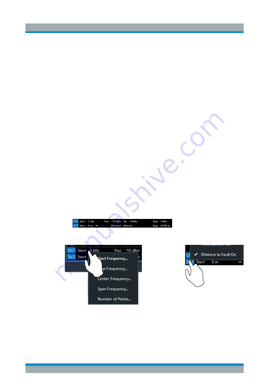
displays an additional "Distance Domain" trace info line below the channel line
Note that all info lines (channel info, trace info,"Distance Domain" trace info) allow
quick access to related parameters via specific context menus:
E.g. "Distance to Fault" can also be enabled/disabled via the context menu of the trace
label (touch and hold for more than one second).
Remote command:
CALCulate<Chn>:TRANsform:DTFault:STATe
Trace Softtool
www.allice.de
Allice Messtechnik GmbH


