In the case of cables, the permissible continuous current depends on the cross-section, insulation material,
design type, and the manner in which the cables have been laid. In the case of overhead lines, an overload of
10 % is permissible.
EXAMPLE
For the Permissible Continuous Current
Cross-linked polyethylene cables (N2XS2Y): 10 kV 150 mm
2
(Cu)
Current-carrying capacity (underground laying): I
max, perm
= 406 A
Selected
K factor
of 1.1
This yields a rated current of I
rated, obj
= 369 A
Parameter:
Thermal time constant
•
Default setting
(_:110) Thermal time constant
=
900 s
The
Thermal time constant
parameter is used to define the tripping characteristics of the stage. If no
data on the
Thermal time constant
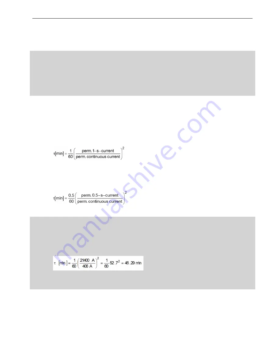
is available, you can determine this from the short-time current-
rating capacity of the cable, for example, from the 1-s current. The 1-s current is the maximum current permis-
sible for 1 s application time. The 1-s current can be found in the cable specifications. Calculate the
Thermal
time constant
according to the following formula:
[fodauers-170309-07.tif, 2, en_US]
If the short-term current-rating capacity is specified for an application time other than 1 s, use the short-time
current instead of the 1-s current. Multiply the result by the specified application time.
For a given short-term current-carrying capacity of 0.5 s, use the following formula:
[fodauers-170309-01.tif, 2, en_US]
EXAMPLE for a Cable
For a cable
Permissible continuous current: I
max, perm
= 406 A
Maximum short-circuit current for 1 s: I
1s
= 21.4 kA
Therefore, for the
Thermal time constant
, it follows
[fokonsta-310510-01.tif, 2, en_US]
with 46.29 min = 2777 s
Parameter:
Cooling time constant
•
Default setting
(_:111) Cooling time constant
=
3600 s
The
Cooling time constant
parameter is used to define the dropout behavior of the stage. Cables and
overhead lines have the same time constant for both heating and cooling. Therefore, set the same value for
the
Cooling time constant
as for the parameter
Thermal time constant
.
Protection and Automation Functions
7.26 Thermal Overload Protection, 3-Phase - Advanced
SIPROTEC 5, High-Voltage Bay Controller, Manual
887
C53000-G5040-C015-9, Edition 11.2017
Summary of Contents for 6MD85
Page 8: ...8 SIPROTEC 5 High Voltage Bay Controller Manual C53000 G5040 C015 9 Edition 11 2017 ...
Page 30: ...30 SIPROTEC 5 High Voltage Bay Controller Manual C53000 G5040 C015 9 Edition 11 2017 ...
Page 46: ...46 SIPROTEC 5 High Voltage Bay Controller Manual C53000 G5040 C015 9 Edition 11 2017 ...
Page 172: ...172 SIPROTEC 5 High Voltage Bay Controller Manual C53000 G5040 C015 9 Edition 11 2017 ...
Page 514: ...514 SIPROTEC 5 High Voltage Bay Controller Manual C53000 G5040 C015 9 Edition 11 2017 ...
Page 1056: ...1056 SIPROTEC 5 High Voltage Bay Controller Manual C53000 G5040 C015 9 Edition 11 2017 ...
Page 1092: ...1092 SIPROTEC 5 High Voltage Bay Controller Manual C53000 G5040 C015 9 Edition 11 2017 ...
Page 1204: ...1204 SIPROTEC 5 High Voltage Bay Controller Manual C53000 G5040 C015 9 Edition 11 2017 ...
Page 1238: ...1238 SIPROTEC 5 High Voltage Bay Controller Manual C53000 G5040 C015 9 Edition 11 2017 ...
Page 1252: ...1252 SIPROTEC 5 High Voltage Bay Controller Manual C53000 G5040 C015 9 Edition 11 2017 ...
Page 1256: ...1256 SIPROTEC 5 High Voltage Bay Controller Manual C53000 G5040 C015 9 Edition 11 2017 ...


