if the pickup value (parameter
Threshold
) of the stage is set to 49.8 Hz and the
Dropout differential
to 100 mHz, the stage will drop off at 49.9 Hz.
Setting example of the underfrequency protection for generators
Underfrequency protection provides an additional protection for the turbine. It has the task of ensuring the
demand of the power plant system by a timely decoupling from the electrical power system. After the decou-
pling from the electrical power system, the turbo set controller sets the generator unit to the rated speed.
Turbogenerators can operate permanently at as little as 95 % of the rated frequency. This requires the appa-
rent power to be reduced by the same factor. A decrease of the frequency leads not only to a higher current
consumption by the inductive loads but is also a hazard to stable operation.
This enables the supply of power plant's own system to continue at rated frequency. The decoupling from the
electrical power system is initiated without delay at 0.95 f
rated
. After the decoupling, the generating unit has to
recover. If it does not, the turbine is stopped for its own protection. In the turbine, underfrequency can lead to
resonances and inadmissible strains of the turbine blades. You can delay the tripping in order to give the
speed controllers sufficient time for a response.
The frequency value to be set depends on the specifications of the power plant operator or the turbine manu-
facturer (speed monitoring). It is approx. 0.94 f
rated
.
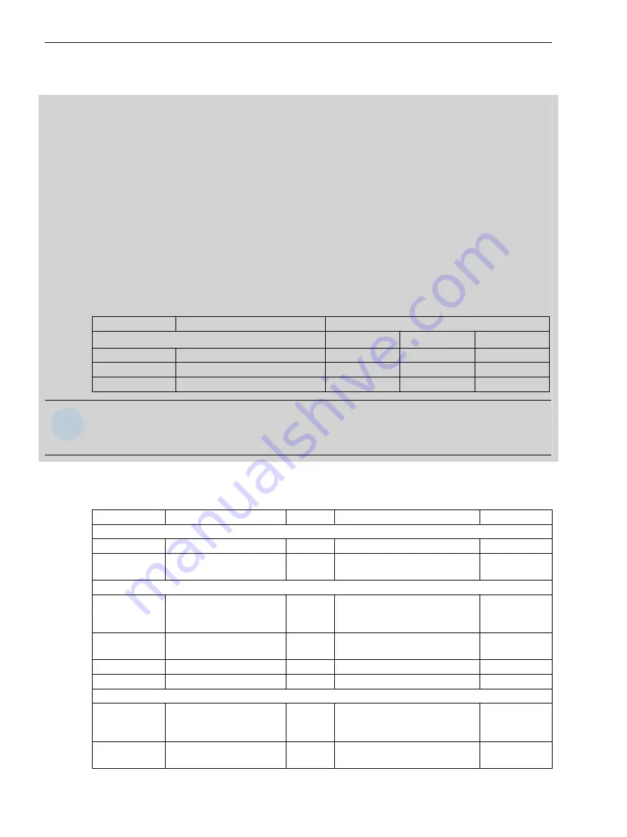
For this application, 3 stages of the underfrequency protection are used. The following table shows a setting
suggestion.
Stage
Caused by
Setting Values
at f
rated
= 50 Hz
at f
rated
= 60 Hz
Delay
f1<
Warning
49,80 Hz
59,80 Hz
10.00 s
f2<
Decoupling from power system
47,50 Hz
57,00 Hz
0.00 s
f3<
Shutdown
47,00 Hz
56,40 Hz
10.00 s
i
i
NOTE
This table shows one example of a possible frequency protection setting. The setting values can differ
depending on the application and the turbine.
Settings
Addr.
Parameter
C
Setting Options
Default Setting
General
_:2311:101
General:Minimum voltage
3.000 V to 175.000 V
37.500 V
_:2311:109
General:Dropout differen-
tial
20 mHz to 2000 mHz
20 mHz
Stage 1
_:61:1
Stage 1:Mode
•
off
•
on
•
test
off
_:61:2
Stage 1:Operate & flt.rec.
blocked
•
no
•
yes
no
_:61:3
Stage 1:Threshold
40.00 Hz to 70.00 Hz
1.00 Hz
_:61:6
Stage 1:Operate delay
0.00 s to 600.00 s
10.00 s
Stage 2
_:62:1
Stage 2:Mode
•
off
•
on
•
test
off
_:62:2
Stage 2:Operate & flt.rec.
blocked
•
no
•
yes
no
7.19.5
Protection and Automation Functions
7.19 Underfrequency Protection
832
SIPROTEC 5, High-Voltage Bay Controller, Manual
C53000-G5040-C015-9, Edition 11.2017
Summary of Contents for 6MD85
Page 8: ...8 SIPROTEC 5 High Voltage Bay Controller Manual C53000 G5040 C015 9 Edition 11 2017 ...
Page 30: ...30 SIPROTEC 5 High Voltage Bay Controller Manual C53000 G5040 C015 9 Edition 11 2017 ...
Page 46: ...46 SIPROTEC 5 High Voltage Bay Controller Manual C53000 G5040 C015 9 Edition 11 2017 ...
Page 172: ...172 SIPROTEC 5 High Voltage Bay Controller Manual C53000 G5040 C015 9 Edition 11 2017 ...
Page 514: ...514 SIPROTEC 5 High Voltage Bay Controller Manual C53000 G5040 C015 9 Edition 11 2017 ...
Page 1056: ...1056 SIPROTEC 5 High Voltage Bay Controller Manual C53000 G5040 C015 9 Edition 11 2017 ...
Page 1092: ...1092 SIPROTEC 5 High Voltage Bay Controller Manual C53000 G5040 C015 9 Edition 11 2017 ...
Page 1204: ...1204 SIPROTEC 5 High Voltage Bay Controller Manual C53000 G5040 C015 9 Edition 11 2017 ...
Page 1238: ...1238 SIPROTEC 5 High Voltage Bay Controller Manual C53000 G5040 C015 9 Edition 11 2017 ...
Page 1252: ...1252 SIPROTEC 5 High Voltage Bay Controller Manual C53000 G5040 C015 9 Edition 11 2017 ...
Page 1256: ...1256 SIPROTEC 5 High Voltage Bay Controller Manual C53000 G5040 C015 9 Edition 11 2017 ...


