193
Servo Parameter
Section 4-8
∆
: Restoring the power/CONFIG is required. (Called Offline User Constant)
Type
User
constant No.
Name
Size
Unit
Lower
limit
Upper
limit
the Support
Tool initial
value
En-
able
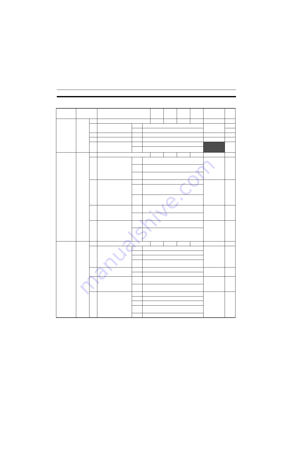
Pn000
Basic function selection switch
2
---
0000H
1FF1H
0000H
∆
0
Rotation direction select
0
CCW direction as forward rotation
0
∆
1
CW direction as forward rotation
∆
1
Control method
0-B
Setting has no effect. Do not set.
0
∆
2
Axis address
0-F
Sets an axis address for servo pack.
0
∆
3
Rotary/Linear startup
select
(Without an encoder)
0
Starts as a rotary type.
0
∆
1
Starts as a linear type.
Pn001
Advanced function selection switch 1
2
---
0000H
1122H
0000H
∆
0
Stopping method in case
of servo-OFF or servo
alarm]
0
Stops the motor using the dynamic brake
(DB).
0
∆
1
Stops the motor using the dynamic brake
(DB), and then cancels the DB.
2
Makes the motor free-run status without
using DB.
1
Stop method in case of
Over travel (OT)
0
The same stopping method as for Pn001.0.
0
∆
1
Makes the motor decelerate to stop with the
torque set in Pn406 as maximum torque, and
the motor will be in servo-lock state.
2
Makes the motor decelerate to stop with the
torque set in Pn406 as maximum torque, and
the motor will be in free-run state.
2
AC/DC power supply
input select
0
DC power supply input not supported: Input
AC power supply to L1, L2, (or L3) terminal.
0
∆
1
DC power supply input supported: Input DC
power supply to (+) 1-(
−
) terminal.
3
Warning code output
select
0
ALO1, ALO2, and ALO3 output only alarm
codes.
0
∆
1
ALO1, ALO2, and ALO3 output both alarm
codes and warning codes. When outputting
the warning codes, the ALM signal output
stays ON (Normal).
Pn002
Advanced function selection switch 2
2
---
0000H
4113H
0000H
∆
0
Speed/position control
option (T-REF allocation)
0
Nil
0
∆
1
Uses T-REF as external torque limit input.
2
Uses T-REF as torque feed forward input.
3
Uses T-REF terminal as external torque limit
input when P-CL and N-CL are enabled.
1
Torque control option (V-
REF allocation)
0
Nil
0
∆
1
Uses V-REF as external speed limit input.
2
Absolute encoder usage
0
Uses an absolute encoder as an absolute
encoder.
0
∆
1
Uses an absolute encoder as an incremental
encoder.
3
Fully-closed PG pulse
usage
0
Not Used
0
∆
1
Uses without phase-C.
2
Uses with phase-C.
3
Uses in reverse rotation mode without phase-
C.
4
Use as reverse rotation mode with phase-C.
Содержание CS1W-MCH71 -
Страница 2: ...CS1W MCH71 CJ1W MCH71 Motion Control Unit Operation Manual Revised June 2008 ...
Страница 3: ...iv ...
Страница 29: ...xxx ...
Страница 33: ...xxxiv ...
Страница 35: ...xxxvi ...
Страница 39: ...xl ...
Страница 69: ...24 Performance Section 1 7 ...
Страница 99: ...54 Connecting MECHATROLINK Devices Section 3 5 ...
Страница 283: ...238 Saving Data Section 5 4 ...
Страница 417: ...372 Command Details Section 6 3 ...


