Page
n
o.
81
Cha
pter
3
Fu
nctio
nsDS.
fm
GE He
alt
h
ca
re
Se
nogra
phe
DS
Re
vision 1
S
er
vic
e Inf
o
rma
tion an
d Pr
oce
dure
s Cla
ss A
23
8507
2-
16-
8EN
Fu
nctiona
l Dia
gr
ams
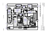
11.
G
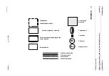
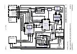
ENERATOR BLOCK DIAGRAM
SWITCH
S1
XJ8
XJ9
XJ4
XJ6
XJ1
XJ13
XJ7
XJ5
XJ10
5
V,
+/
‐
12
V
XJ1
Kv
‐
mA
Board
701
PL1
XJ1
XJ3
XJ2
XJ4
XJ5
XJ1
XJ3
XJ8
XJ11
XJ4
X9
XJ1
X1
X5
X8
GKA/2
GKA/1
to
Stator
Motor
X3
X4
X7
X10
X11
X12
X6
XJ2
XJ6
XJ4
XJ8
XJ10
XJ7
XJ9
AUTO
‐
TRANSFO
XJ11
D27
‐
AK D25
‐
AK
F3
‐
2
XJ9
XJ10
XJ6
C1
‐
P
XJ7
C1
‐
M
C2
XJ2
XJ3 XJ1
FAN
T°
S2
T°
S1
Heat
Sink
Inverter
300
PL1
C1
‐
+
C2
‐
+
C3
‐
+
C4
‐
+
C5
‐
+
C6
‐
+
C7
‐
+
C8
‐
+
TR1
TR1
C1
AC
Mains
via
Line
Supply
Cable
FUSE
PHASE
2
OR
NEUTRAL
FUSE
PHASE
1
RELAY
K1
1
3
13
A1
2
4
14
A2
1
2 3
4
SELF
L1
C10
C9
XJ2
XJ3
XJ1
BR1
T°
TH1
0
V,
+
25
0
Vdc
from
X
‐
ray
Console
from
Gantry
Optical
Fibers
0
V,
+
250
Vdc
0
V,
+
250
V
DC
to/from
X
‐
Ray
Room
Ext.
Seno
On
Lamp
Ext.
X
‐
Ray
On
Lamp
Ext.
Room
Door
Switch
Emergency
Stop
Button
to/from
Gantry
27
V
AC
25
0
V
AC
F5
F4
mA
RETURN
HV
Connector
X
‐
Ray
Tube
Housing
Return
HV
Cable
‐
4
Wires
To
Gantry
GKC
XJ3
XJ2
Kv
Mea
su
re
to
Gantry
AC
Supply
PH2
PH1
XJ6
XJ7
XJ9
To
MDR

