


GE Healthcare
Senographe DS
Revision 1
Service Information and Procedures Class A 2385072-16-8EN
Job Card PHY A003 - Gantry and Control Station Installation
Page no. 403
Chapter 6
JC-PHY-A-003.fm
7
INSTALL AND ANCHOR THE GANTRY
Note:
Do not remove the packing from the Image Receptor until all operations that can cause dust and
disturbance in the area have been completed.
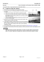
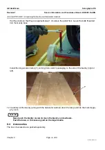
1. Wheel the Gantry to its correct position, with the three baseplate mounting holes aligned with the
three holes drilled in the floor.
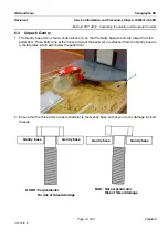
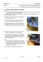
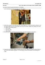
2. Place the three flat round jack feet (1) on the floor with
their nipples facing upwards.
3. Turn the three jacking bolts downwards until their hol-
lowed ends engage with the nipples of the jack feet.
4. Use the ratchet wrench with a 22 mm socket to jack up
progressively the Gantry. Do this turning the three jack-
ing bolts (2), until the wheeled bars are clear of the floor.
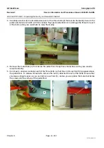
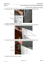
5. Use the 8 mm allen wrench to remove the screws (3)
securing the wheeled bars (4). Remove the bars.
6. Turn the jacking bolts to lower the Gantry, ensuring that
the baseplate remains as horizontal as possible, until it
is fully supported by its baseplate. Remove the three
jacking bolts completely.
Note:
The three jack feet remain below the Gantry base-
plate. If the floor is not perfectly even, use the three
leveling screws provided in the installation kit. to level
the Gantry base. Insert the min place of the jacking
bolts to push on the jack feet.
7. Bolt the Gantry to the prepared inserts in the floor.
1
2
3
4


