


GE Healthcare
Senographe DS
Revision 1
Service Information and Procedures Class A 2385072-16-8EN
Job Card D/R A190 - Gantry CPU Board
Page no. 1133
Chapter 9
JC-DR-A-190.fm
6-2
Replacing the Gantry CPU Board
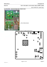
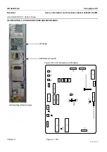
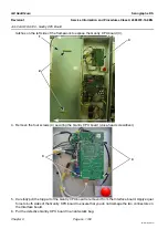
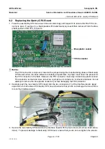
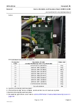
1. Take the new Gantry CPU board out of its anti-static bag, and inspect it to ensure that the TP2 con-
nector is open. If a jumper (i.e. black plastic with metal insets) is present then remove it from the blue
plastic socket of the TP2 connector.
! Notice:
The TP2 connector is only ever closed with a jumper during the manufacturing phase of the Gantry
CPU board, when the base software is initially programmed. A jumper must never be present on
the TP2 connector in the field. However, the TP2 connector must only contain blue plastic socket.
This socket is normal and does not act as a jumper as it contains no conductive material. Do not
attempt to remove the blue plastic socket as you risk damaging the TP2 connector.
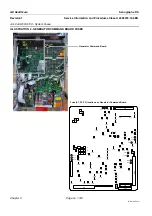
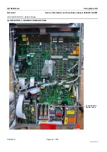
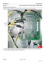
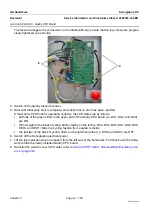
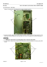
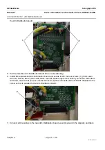
2. Carefully push the new Gantry CPU board into the two connectors (1) of the Interface board. Apply
equal force to both sides of the Gantry CPU board to ensure that you do not damage the two connec-
tors on the Interface board.
3. Secure the new Gantry CPU board to the Interface board with the four screws (2) (cross-head screw-
driver). To prevent damage to the Gantry CPU board, ensure that you do not overtighten the screws.
TP2 Connector
Blue plastic socket
1


