


Chapter 9
Page no. 1596
JC-DR-A-410.fm
GE Healthcare
Senographe DS
Revision 1
Service Information and Procedures Class A 2385072-16-8EN
Job Card D/R A410 - Inverter Board 300-PL1
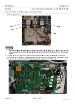
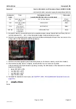
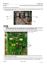
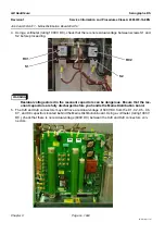
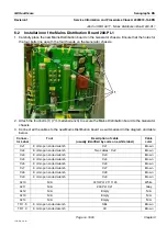
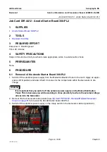
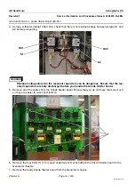
4. Using a voltmeter (rating 1000 V DC), check that there is no residual voltage between screws S1 and
S2 before proceeding.
WARNING
Residual voltage stored in the resonant capacitors can be dangerous. Ensure that the res-
onant capacitors are fully discharged before you handle the Inverter board.
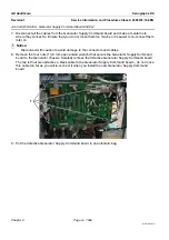
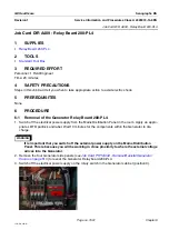
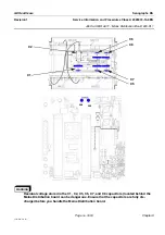
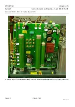
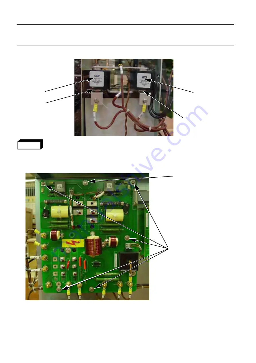
5. Remove all of the cables from the Inverter board (10 mm open ended wrench and small screwdriver).
Ensure that you do not move them too much so they are easier to re-connect later on.
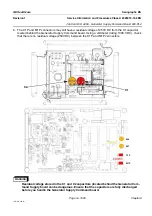
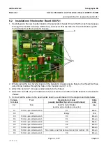
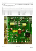
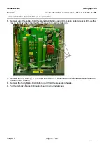
6. Remove the six bolts (1) and the one nut (2) (7 mm open ended wrench) which attach the Inverter
board to the Generator chassis.
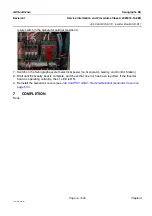
7. Remove the faulty Inverter board from the Generator chassis. Pay attention since some of the cables
pass through holes in the Inverter board. Put the defective Inverter board in an anti-static bag.
S2
S1
RC2
RC1
1
2


