Page
n
o.
75
Cha
pter
3
Fu
nctio
nsDS.
fm
GE He
alt
h
ca
re
Se
nogra
phe
DS
Re
vision 1
S
er
vic
e Inf
o
rma
tion an
d Pr
oce
dure
s Cla
ss A
23
8507
2-
16-
8EN
Fu
nctiona
l Dia
gr
ams
5.
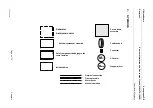
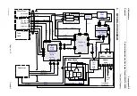
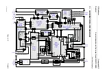
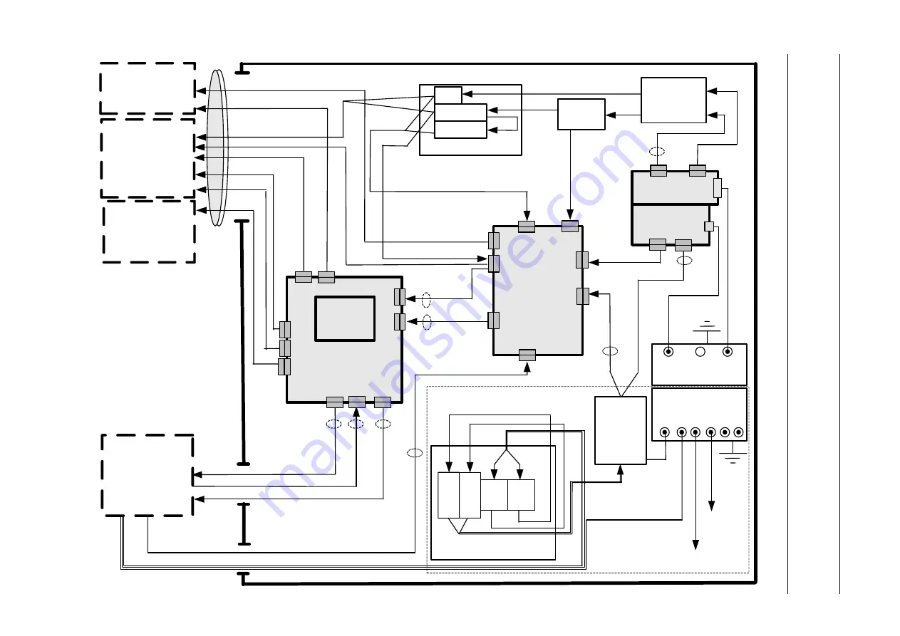
MPCB BLOCK DIAGRAM
To
XR
Tube
W216
J6
J7
J4
J5
J1
J2
J10
J9
J6
J7
J8
J3
J1
W402
Generator
W315
W314
W210
W119
W121
W217
W208
SYS
‐
Bus1
W209
J8
J4
J5
J2
J1
J138
J137
X1
F1
F2
F1/2
F1/1
F2/1
F2/2
Arm
Distrib.B.
Lift
+
Rot.
Nd.
Arm
Distrib.B.
E.Stop
R
‐
Butt.
E.Stop
L
‐
Butt.
Lift
+
Rot.
Nd.
Lift
+
Rot.
Nd.
J3
12
Vd
c
to
PD
U
AC
supply
48
Vdc2
(
‐
)
48
Vdc3
48
vdc1
48vdc
LP
Fu
se
ch
ec
k
Th
er
mo
swit
ch
SY
S
POS
Bus
POS
Bus
1
Serial
link
Rx
Serial
link
Tx
GridSync
DC
Control
J2
AC
PD
U
Su
pp
ly
48
vdc
LP
1
48
vd
c
LP
2
48vdc
HP
AC
Su
pp
ly
N,
P
N',
P'
GND
bar
G101
X4
X3
B
B2/1
B2/2
P'
P
N'
N
Bulkhead
Area
W315
Comp.
Arm
Column
Tube
Head
N
N'
P'
P
GND
bar
G102
To
Bulkhead
Cover
plate
To
GND
Bar
B
B1/1
B1/2

