


Chapter 9
Page no. 1250
JC-DR-A-229.fm
GE Healthcare
Senographe DS
Revision 1
Service Information and Procedures Class A 2385072-16-8EN
Job Card D/R A229 - Rotation Brake
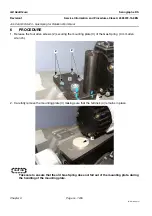
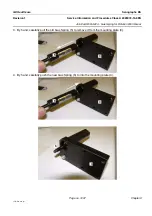
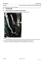
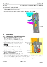
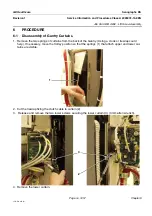
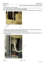
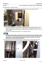
3. Loosen the pulling screws (7) until they protrude by 3 mm from the holder plate.
4. Tighten the pushing screws (8) to reduce the gap between the mobile and non mobile parts of the
brake. View the gap through the four openings and continue until the gap is close to 0 mm (starting
value for the next step).
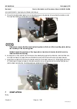
5. Connect the Brake cable (W219) to the Rotation Board (connector J6).
6-3
Brake Positioning Adjustments
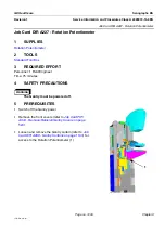
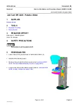
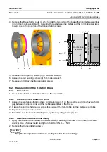
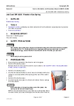
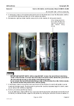
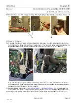
1. Use a 0.15 mm feeler gauge as shown in the illustration
to avoid touching the springs:
1. Try to insert the feeler gauge through the left side of
the opening (E), loosen the pushing screw until the
feeler gauge slips in,
2. Try to insert the feeler gauge through the right side of
the opening (F), loosen the pushing screw until the
feeler gauge slips in,
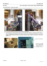
3. Try to insert the feeler gauge through the right side of
the opening (G), loosen the pushing screw until the
feeler gauge slips in,
4. Try to insert the feeler gauge through the left side of
the opening (H), loosen the pushing screw until the
feeler gauge slips in,
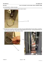
2. Check for each opening that:
1. The 0.15 mm feeler gauge slips in.
2. The 0.18 mm feeler gauge does not enter. If it does, reinsert the 0.15 mm feeler gauge and
retighten the appropriate pushing screw.
3. Tighten the four pulling screws.
6-4
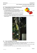
Check the Rotation Movement
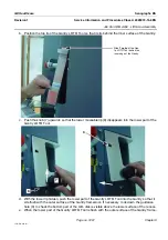
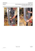
1. Move the compression paddle out of compression. Then check that all four sets of arm left/right con-
trol buttons are operational (check each button for rotation movement of column).
2. Rotate the arm to its left and right limits. Software preset limits should stop movement (185° counter-
clockwise, 165° clockwise).
6-5
Brake Fine Adjustment
During arm movement, check for any noise that indicates excessive friction or binding.
7
COMPLETION
None
E
G
H
F


