


GE Healthcare
Senographe DS
Revision 1
Service Information and Procedures Class A 2385072-16-8EN
Job Card D/R A233 - Lift Screw Assembly Top Brake
Page no. 1283
Chapter 9
JC-DR-A-233.fm
7-2
Re-assembly of the new Gantry Lift Screw Brake
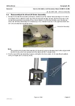
1. Prepare to top of the Lift Screw Assembly so that the screw’s hexagonal shape is in the correct orien-
tation for the Lift Screw Assembly Top Brake to fit onto it. Turn the Lift Screw so that the corner of the
screw’s hexagonal shape is pointing towards the edge of the Gantry wall.
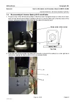
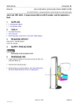
2. Place the Lift screw Assembly Top Brake (2) so that the corner with the cable (2) is on the right hand
side (when viewing the Gantry wall front on) as illustrated below.
1
Gantry Wall
Top View
Brake cable in this corner
3
2
4


