GE Healthcare
Senographe DS
Revision 1
Service Information and Procedures Class A 2385072-16-8EN
Job Card D/R A406 - Generator Command Board 400-PL1
Page no. 1571
Chapter 9
JC-DR-A-406.fm
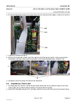
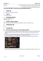
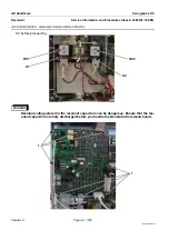
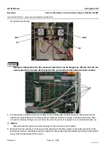
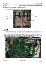
5. The Generator Command board is located on the top left of the Generator. Disconnect all the cables
from the Generator Command board and make a mental note where they connect to. Ensure that you
do not move them too much so it is easier to re-connect them later on.
! Notice:
Disconnect with caution to avoid damage to the connectors and cables.
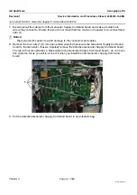
6. Remove the eight screws (1) that secure the Generator Command board (4 mm allen wrench) to the
Generator chassis, and carefully remove the defective Generator Command board.
7. Make a note of the defective Generator Command board current jumper settings. There are two sets
of jumpers JP1/JP2 below the XJ8 connector, and JP3/JP4 above the XJ8 connector. These jumpers
determine the room lamps and door configuration.
8. Put the defective Generator Command board in an anti-static bag.
6-2
Installation of the Generator Command Board 400-PL1
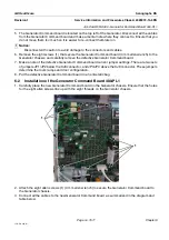
1. Carefully place the new Generator Command board on the Generator chassis. Ensure that the holes
for the eight allen screws line up with the eight threads on the Generator chassis.
2. Attach the eight allen screws (1) (4 mm allen wrench) to secure the Generator Command board to
the Generator chassis.
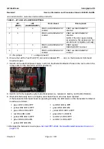
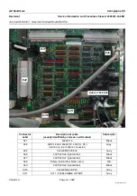
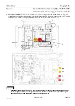
3. Connect all the cables to the new Generator Command board as summarized in the diagram and
table below.
1
1

