


Chapter 9
Page no. 1372
JC-DR-A-280.fm
GE Healthcare
Senographe DS
Revision 1
Service Information and Procedures Class A 2385072-16-8EN
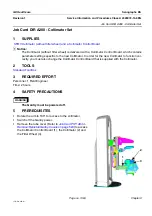
Job Card D/R A280 - Collimator Set
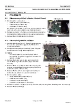
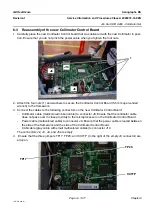
5. Power on the Gantry and check that no errors are raised on the Gantry LCD display.
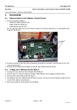
6. Check that the LED states are as follows. For more information about the behavior and states of the
Collimator Control board LEDs, refer to
Collimator Control Board PL403
.
6-4
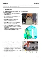
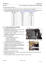
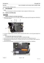
Reassembly of the Collimator
1. Replace the new Collimator (1).
2. Reattach the four screws (2, two each side) securing
the Collimator (4 mm allen wrench).
3. Use a torque wrench to tighten the four screws (2, two
each side) to 3.0 Nm
±
0.2 Nm.
4. Apply Blue Loctite 243 around the heads of the four
screws (2, two each side).
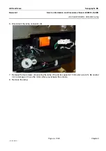
5. Reconnect four cables.
-
Lamp cable W503 (flying lead) (3)
-
Collimator cable W501 (4)
-
Filter wheel cable W505 (5)
-
Filter wheel cable W507 or W509 (6)
6. Reattach the two screws securing the connector pro-
tection box (7) (small cross-head screwdriver).
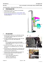
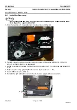
7. Replace the X-ray containment box. If necessary, first
reattach the two screws (8) which secure the fan pro-
tection box (3 mm allen wrench).
8. Reattach the four screws (9, two each side) which
secure the X-ray containment box (10) (4 mm allen
wrench).
9. Reconnect the plate and FOV button.
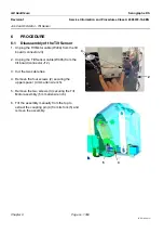
10. Reattach the two screws (11, one each side) securing the rear plate (12) which supports the FOV
button (4 mm allen wrench).
11. Check visually that all screws securing the Collimator are well mounted.
LED Label
LED Color
LED Status
DS1
Green
ON
DS2
Green
OFF or ON
DS3
Green
ON
DS4
Green
ON
DS5
Green
ON
DS6
Green
OFF
DS7
Red
OFF
DS8
Red
OFF
DS9
Red
OFF
DS10
Red
OFF
2
1
12
7
10
9
8
11
3
5
6
4


