


GE Healthcare
Senographe DS
Revision 1
Service Information and Procedures Class A 2385072-16-8EN
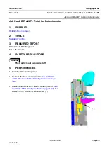
Job Card D/R A230 - Rotation Gas Spring
Page no. 1253
Chapter 9
JC-DR-A-230.fm
6-2
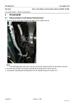
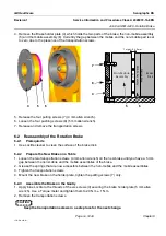
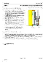
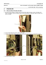
Reassembly of the Gas Spring
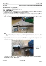
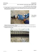
1. Attach the lower fixing part (6) to the new Gas Spring.
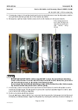
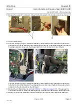
2. Carefully position the new Gas Spring behind the
Rotation Board, feel for the upper fixing part. Turn the
new Gas Spring clockwise until it is firmly secured to
the upper fixing part.
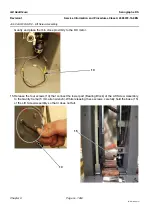
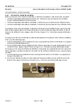
3. Push the lower end of the Gas Spring and the lower
fixing part on to the lower support.
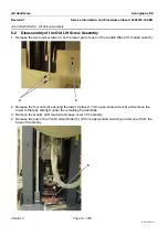
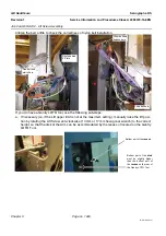
4. Insert and tighten the screw (5) into the bearing
(6 mm allen wrench).
5. Tighten the fifth screw (4) of the lower support plate
(6 mm allen wrench). While tightening the fifth screw
of the lower support plate, ensure that the bottom of
the Gas Spring (8) is aligned (within approximately
2 mm) with the bottom of the arm (9).
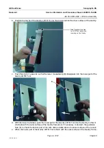
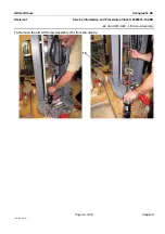
6. Tighten the four screws (3) of the lower support plate
by half a turn (6 mm allen wrench).
7. Place the U-Plate (2) on the lower support, and
secure it with the four screws (1) (4 mm allen
wrench).
6-3
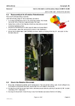
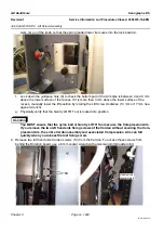
Check the Rotation Movement
1. Move the compression paddle out of compression. Then check that all four sets of arm left/right con-
trol buttons are operational (check each button for rotation movement of column).
2. Rotate the arm to its left and right limits. Software preset limits should stop movement (185° counter-
clockwise, 165° clockwise).
3. During arm movement, check for any noise that indicates excessive friction or binding.
7
COMPLETION
None
8
9


