Chapter 3
Page no. 252
Indicators and Switches.fm
GE Healthcare
Senographe DS
Revision 1
Service Information and Procedures Class A 2385072-16-8EN
Central Listing
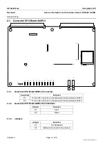
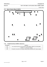
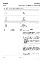
2-3-1.
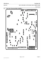
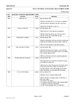
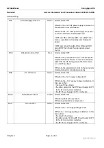
Generator Command Board 400PL1 Connectors
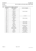
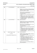
2-3-2.
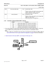
Generator Command Board 400PL1 Fuses
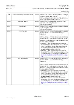
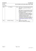
Connector
Function
XJ1
To the XJ1 connector on the Supply Command Board 200PL2 (standby power supply)
XJ2
To the XJ5 connector on the Supply Command Board 200PL2 (250 V)
XJ3
To the CN2 connector on the BT Power Supply 400T1 (power supply ±12 V, +5 V)
XJ4
To the HV Tank (heater, bias)
XJ5
To the XJ1 connector on the kVmA Board (HV Tank control)
XJ6
To XJ1 the connector on the Anode Starter Board (+12 V, control signals)
XJ7
To the XJ1 connector on the Inverter Board (control signals)
XJ8
From X-ray Console Cable (27 V, Rx/Tx signal, PREP, and GRAPHIE signals)
XJ9
To the XJ1 connector on the Generator Interface Board 400PL2 (power supply ±12 V, +5 V)
XJ10
To the XJ2 connector on the Generator Interface Board 400PL2 (control signals)
XJ11
Not Applicable
XJ12
To the Rx button
XJ13
To the XJ11 connector on the Supply Command Board 200PL2 (control signals)
Fuse
Specification
PN
Function
F1
250 V, 2.5 A, Time delay
99194291
+5 V BT supply
F2
-12 V BT supply
F3
+12 V BT Supply


