Chapter 9
Page no. 1656
JC-CAL-A-003.fm
GE Healthcare
Senographe DS
Revision 1
Service Information and Procedures Class A 2385072-16-8EN
Job Card CAL A003 - X-Ray Tube Focal Bias Voltage Scale Factor
6-1
Preparation
1. Turn the Senographe OFF.
2. Open the HV converter control signal inputs by disconnecting flat cable WG8 from generator com-
mand board 400-PL1 connector XJ7. This eliminates any possibility of energy build-up in the HV unit
during this calibration procedure.
3. Disconnect the Senographe HV cable at the HV tank end.
4. Connect the HV cable to the HV unit / cable adaptor (36003399).
5. Connect the HV unit / cable adaptor to the Senographe HV tank.
6. Connect a multimeter (in DC voltmeter mode) between common (C) and the focal bias voltage wire
(G) (see illustrations 1 and 2).
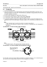
ILLUSTRATION 1 - HV UNIT HV CABLE ADAPTOR 36003399
Note:
For safety reasons, -HT is permanently connected to ground
ILLUSTRATION 2 - HV CABLE CONNECTOR PIN CONNECTION DIAGRAM
The HV cable connector is marked with the standard X-ray industry markings (L, S, C and G). However,
the functions of the corresponding conductors in the Senographe are as follows:
L = track 1 (Mo) filament supply
S = track 2 (Rh) filament supply
C = filament supply return and X-ray tube cathode HVG = focal bias voltage supply
L
C
S
G
S
G
L
C
Bias measurement
Ground (+HV)
BIAS
TRACK 1 (Mo)
TRACK 2 (Rh)
-HT
Ground (+HV)
BIAS
TRACK 1 (Mo)
TRACK 2 (Rh)
-HT
From HV tank
To X Ray tube
HV cable
shield
Track 2 (Rh): jumper or ammeter
Track 1 (Mo): jumper or ammeter
C
G
L
C
S
G
POLARIZING TAB
NOTE: THIS IS A HEAD-ON VIEW
OF THE HV CABLE CONNECTOR
AFTER BEING DISCONNECTED
FROM THE HV UNIT.

