GE Healthcare
Senographe DS
Revision 1
Service Information and Procedures Class A 2385072-16-8EN
Job Card ELE A007 - Line Resistance Measurement
Page no. 547
Chapter 7
JC-ELE-A-007.fm
Job Card ELE A007 - Line Resistance Measurement
Chapter 7
1
SUPPLIES
None
2
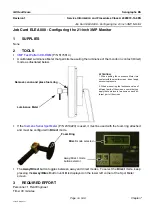
TOOLS
3
REQUIRED EFFORT
Personnel: 1 Field Engineer
Time: 40 minutes
4
SAFETY PROCEDURES
During the procedures in this Job Card, you are in close proximity to circuits operating at line voltage -
take appropriate precautions.
5
PREREQUISITES
You must follow the chronological order given in the Installation Job Card
Installation Steering
.
Note:
Make sure that the X-ray Console is connected to the Generator.
6
PROCEDURE
If the resistance at the line input to the Senographe generator is too high, there will be a significant volt-
age drop when the generator draws maximum power. This procedure checks that the resistance is within
acceptable limits.
6-1
Preparation
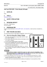
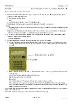
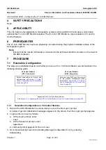
1. Switch off the system; set the Generator power switch 200-S1 to the 0 position.
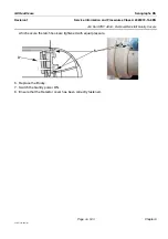
2. Disconnect voltage selection wire SEL from its lug on the Mains Distribution Board 200-PL1; recon-
nect it to the 0 V lug.
! Notice:
The 0 V position of the SEL wire is reserved exclusively for this line resistance measurement. The
Senographe cannot function normally when the SEL wire is in this position. Do not attempt to
switch on the Senographe at this point - follow the instructions below.
3. Connect the multimeter to the input end of the power switch 200-S1; Note and write down the
observed value of the open-circuit line voltage V1:
V1 =......................................
6-2
Procedure
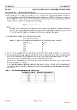
1. Turn on the AC supply: set the generator switch 200-S1 to the 1 position.
Note:
Read the next step completely before performing it. You only 3 seconds have to read the voltmeter;
if you miss the reading you must wait about 15 minutes to repeat it
.

