


GE Healthcare
Senographe DS
Revision 1
Service Information and Procedures Class A 2385072-16-8EN
Job Card D/R A413 - BT Power Supply 400-T1
Page no. 1615
Chapter 9
JC-DR-A-413.fm
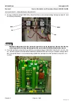
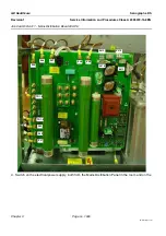
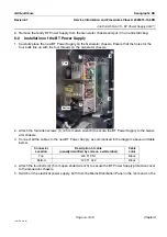
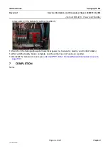
8. Remove the faulty BT Power Supply from the Generator chassis and put it in an anti-static bag.
6-2
Installation of the BT Power Supply
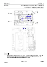
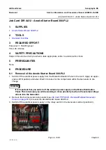
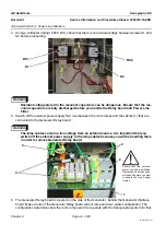
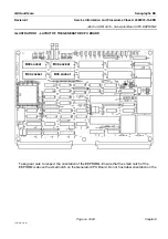
1. Carefully place the new BT Power Supply on the Generator chassis. Ensure that the holes for the
four bolts line up with the four threads on the Generator chassis.
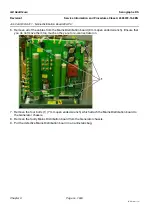
2. Attach the four allen screws (1) (2.5 mm allen wrench) to secure the BT Power Supply to the Gener-
ator chassis.
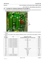
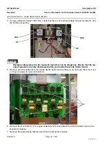
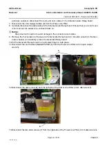
3. Connect all the cables to the new BT Power Supply as summarized in the diagram above and table
below.
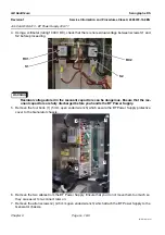
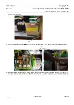
4. Attach the four bolts (2) (5 mm open ended wrench) to secure the BT Power Supply protective cover
to the Generator chassis.
5. Switch on the electrical power supply, both from the Mains Distribution Panel in the room and on the
Connector
Location
Description of cable
(usually identified by code on a white label)
Cable
color
Top
400 T1 CN1
Black
Bottom
400 T1 XJ2
Black
1
2
1
2
Bottom
Top