


GE Healthcare
Senographe DS
Revision 1
Service Information and Procedures Class A 2385072-16-8EN
Job Card D/R A194 - AC/DC Module
Page no. 1159
Chapter 9
JC-DR-A-194.fm
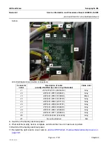
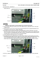
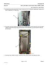
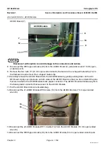
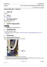
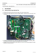
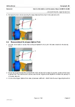
5. Connect the J137/PL102-W106 cable (6) and the J138/PL107-W107 cable (7) to the AC/DC Board.
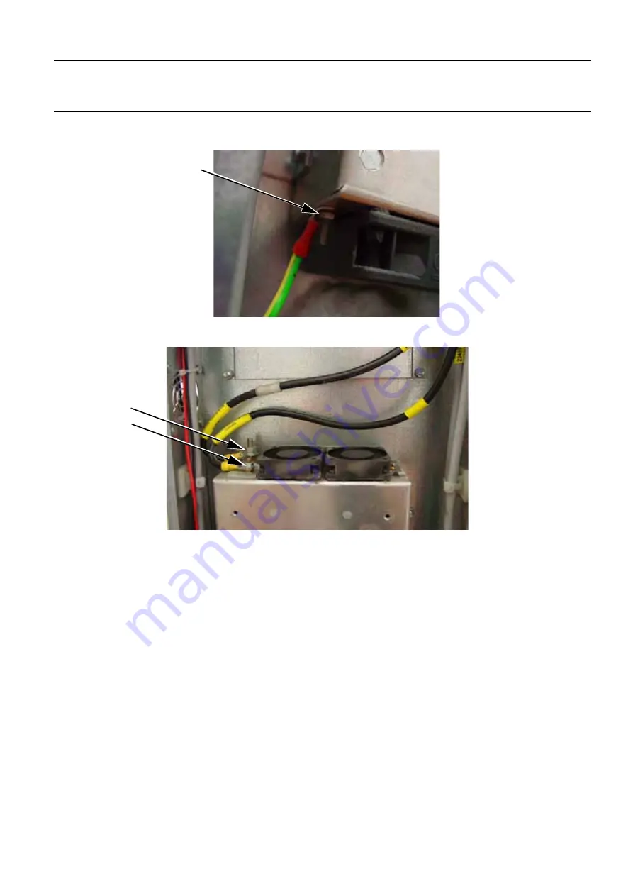
6. Connect the W005 ground cable (8) to the new AC/DC Module (5 mm open ended wrench).
7. Connect the J2-AC/DC Module W1112 cable (9) to the new AC/DC Module (7 mm open ended
wrench).
8. Connect the J1-AC/DC Module W109 cable (10) to the new AC/DC Module (10 mm open ended
wrench).
9. Switch on the Gantry electrical power.
10. Wait until the Gantry boot is complete, and check that no error has been reported.
11. Switch off the Gantry electrical power.
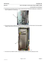
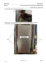
12. Re-attach the ground cable to the bottom metal cover (8 mm open ended wrench) and replace it over
the framework to cover the newly installed AC/DC Board.
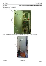
13. Lift the top metal panel up to release it from the left side of the framework and replace it over the
framework.
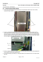
14. Reinstall the left column cover; refer to
Job Card PHY A044 - Remove/Reinstall Gantry Covers
7
COMPLETION
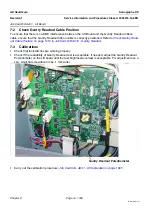
After changing the AC/DC Board, no calibrations are necessary.
8
10
9


