Chapter 9
Page no. 1680
JC-CAL-A-021.fm
GE Healthcare
Senographe DS
Revision 1
Service Information and Procedures Class A 2385072-16-8EN
Job Card CAL A021 - Arm Rotation Calibration
6-2-1
Set the 0° position
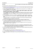
1. You are asked to move the arm to the 0° position. Press and hold the appropriate rotation movement
control button. Stop the arm at the 0° position.
2. Check that the arm is in the correct position (0° ±0.5°) by using a spirit level or similar device to check
that the top of the digital detector is horizontal.
3. If necessary, use the movement control buttons to adjust the arm as required until it is in the 0° posi-
tion.
4. When the arm has been correctly positioned, press the collimator FOV size button (behind the tube
head) to signal completion of the 0° adjustment.
6-2-2
Set the 185° position
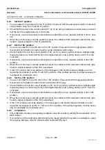
1. You are now asked to move the arm to the 185° position. Press and hold the appropriate rotation
movement control button to rotate the arm counter-clockwise until it stops.
2. Check that the arm is in the correct position (185° ±0.5°) by using a spirit level and a suitable angle
measuring device to check that the top of the digital detector (now pointing down) is at 5° from the
horizontal.
3. If necessary, use the movement control buttons to adjust the arm as required until it is in the 185°
position.
4. When the arm has been correctly positioned, press the collimator FOV size button (behind the tube
head) to signal completion of the 185° adjustment.
5. If the 185° position cannot be attained, or the message on the Gantry readout indicates an error,
repeat the procedures to set the 0° and 185° positions. If the problem persists, it will be necessary to
investigate for a hardware error.
6-2-3
Set the -165° position
1. You are now asked to move the arm to the -165° position. Press and hold the appropriate rotation
movement control button to rotate the arm clockwise until it stops.
2. Check that the arm is in the correct position (-165° ±0.5°) by using a spirit level and a suitable angle
measuring device to check that the top of the digital detector (now pointing down) is at 15° from the
horizontal.
3. If necessary, use the movement control buttons to adjust the arm as required until it is in the -165°
position.
4. When the arm has been correctly positioned, press the collimator FOV size button (behind the tube
head) to signal completion of the -165° adjustment.
5. If the -165° position cannot be attained, or the message on the Gantry readout indicates an error,
repeat the procedures to set the 0°, 185° and -165° positions. If the problem persists, it will be neces-
sary to investigate for a hardware error.
6-2-4
Completion
•
If the calibration has been successfully completed, save the results by clicking the
Save
button on the
AWS Screen.
•
If you wish to exit the calibration without saving the results (leaving the system un-calibrated or using
the previous settings), click the
Cancel
button on the AWS Screen.


