


GE Healthcare
Senographe DS
Revision 1
Service Information and Procedures Class A 2385072-16-8EN
Job Card D/R A232 - Lift Screw Assembly
Page no. 1273
Chapter 9
JC-DR-A-232.fm
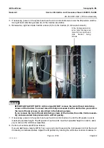
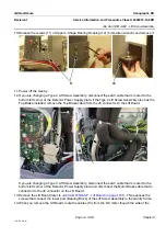
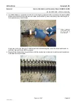
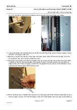
wrench) until the two right hand side fixing screw holes (8) of the Arm Frame are visible.
9. Insert and tighten the right left hand screws (8) of Cardan Assembly, ensure that you apply a torque
of 20 Nm and apply Loctite 270.
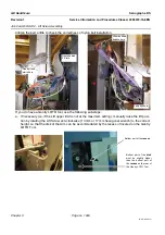
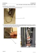
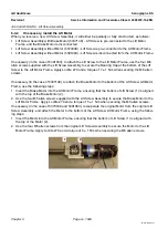
10. Before you tighten the screws on the upper and lower parts of the Lift Screw Assembly, move the
Compression Arm up and down at least two times.
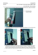
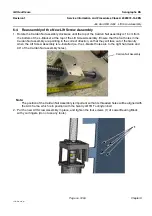
11. Move the Compression Arm down and tighten the four screws (9) that connect the lower part (Bear-
ing Block) of the Lift Screw Assembly to the Gantry frame (5 mm allen wrench). Ensure that you
apply a torque of 10 Nm and apply Loctite 270. Fully tighten the four screws in the following "cross"
order top left, bottom right, bottom left, top right.
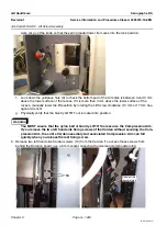
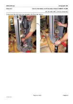
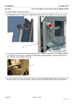
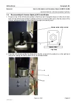
12. Move the trolley up, and tighten the screws (10) of the upper part of the Lift Screw Assembly. Ensure
that you apply a torque of 10 Nm and apply Loctite 270. Fully tighten the four screws in the following
8
7
9


