


GE Healthcare
Senographe DS
Revision 1
Service Information and Procedures Class A 2385072-16-8EN
Job Card PHY A030 - Generator and Gantry Disconnection Reconnection
Page no. 497
Chapter 6
JC-PHY-A-030.fm
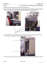
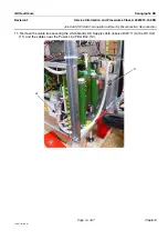
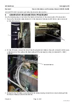
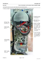
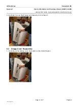
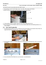
13. Ensure that the orange coupling block is securely positioned on the L-shaped bracket located on the
Auto Transformer (11).
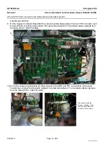
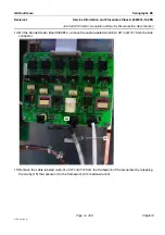
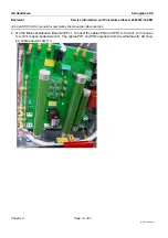
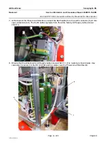
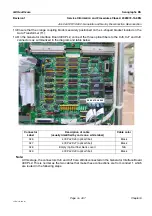
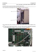
14. On the Generator Interface Board 400 PL2, connect the three optical fibers to the XJ6, XJ7 and XJ9
connectors as summarized in the diagram and table below.
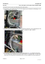
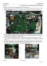
Note:
At this stage, the connectors XJ4 and XJ10 are still disconnected on the Generator Interface Board
400 PL2. This is normal as the two cables that make these connections are from conduit 1, which
are routed in the following steps.
Connector
Label
Description of cable
(usually identified by code on a white label)
Cable color
XJ6
400 PL2 XJ6 (optical fiber)
Black
XJ7
400 PL2 XJ7 (optical fiber)
Black
XJ8
Empty (optical fiber blank cover)
N/A
XJ9
400 PL2 XJ9 (optical fiber)
Black
XJ6 XJ7 XJ8 XJ9


