


GE Healthcare
Senographe DS
Revision 1
Service Information and Procedures Class A 2385072-16-8EN
Job Card D/R A319 - Rotative Arm
Page no. 1495
Chapter 9
JC-DR-A-319.fm
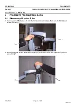
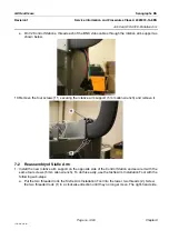
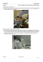
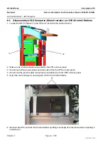
c. Attach the top two screws (4) to secure the top of the rotative arm support (5 mm allen wrench).
d. Carefully pull the acrylic support block to remove it from the two threaded rods. Unscrew the two
threaded in an anti-clockwise direction to remove them from the Control Station framework.
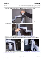
e. Attach the bottom two screws (5) to secure the top of the rotative arm support (5 mm allen
wrench).
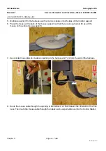
f. Use the torque wrench to tighten the four screws to 9.5 Nm
±
0.5 Nm.
g. Apply Blue Loctite 243 around the heads of the four screws.
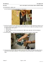
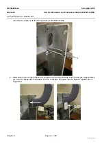
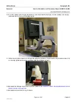
2. Pass each of the monitor cables that you stored on top of the Control Station keyboard through the
opening of the rotative arm support. To do this easily, proceed as described in the following sub-
steps.
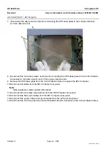
a. On V3/V4 Control Stations, thread the DVI video cable through the opening of the rotative arm
support as shown below.
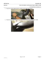
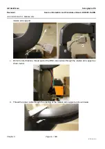
b. On V3/V4 Control Stations, thread the ferrite ring (6) of the DVI video cable inside the rotative arm
support. While keeping the DVI connector outside (7) move the DVI video cable to the top of the
4
5
6
7


