Chapter 9
Page no. 1370
JC-DR-A-280.fm
GE Healthcare
Senographe DS
Revision 1
Service Information and Procedures Class A 2385072-16-8EN
Job Card D/R A280 - Collimator Set
6
PROCEDURE
6-1
Disassembly of the Collimator Control Board
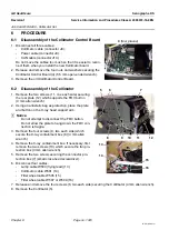
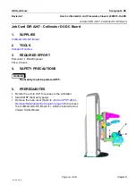
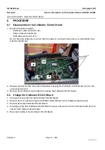
1. Disconnect all three cables:
-
Collimator cable (connector J8).
-
Power cable (connector J9).
-
CAN cable (connector J10).
Do not move the cables too much so that it is easier to recon-
nect them when you install the new Collimator board.
2. Release and remove the four nuts and washers securing the
Collimator Control Board (4) (5.5 mm open-ended wrench).
3. Remove the old Collimator Control Board.
6-2
Disassembly of the Collimator
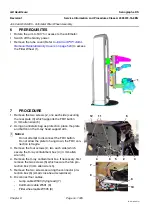
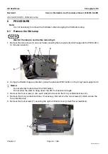
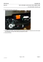
1. Remove the two screws (11, one each side) securing
the rear plate (12) which supports the FOV button
(4 mm allen wrench).
2. Using an antistatic bag as protection, place the plate
and button on the X-ray head support arm.
! Notice:
Do not attempt to disconnect the FOV button.
Do not allow the plate to hang down; the FOV con-
nection is fragile.
3. Remove the four screws (9, two each side) which
secure the X-ray containment box (8) (4 mm allen
wrench).
4. Remove the X-ray containment box. If necessary, first
remove the two screws (10) which secure the fan pro-
tection box (3 mm allen wrench).
5. Remove the two screws securing the connector pro-
tection box (7) (small cross-head screwdriver).
6. Disconnect four cables.
-
Lamp cable W503 (flying lead) (13)
-
Collimator cable W501 (14)
-
Filter wheel cable W505 (15)
-
Filter wheel cable W507 or W509 (16)
7. Release and remove the four screws (6, two each side) securing the Collimator (4 mm allen wrench).
8. Remove the Collimator (5).
4
(four places)
6
5
12
7
8
9
10
11
13
15
16
14

