


GE Healthcare
Senographe DS
Revision 1
Service Information and Procedures Class A 2385072-16-8EN
Job Card D/R A216 - Arm Control Keypads
Page no. 1221
Chapter 9
JC-DR-A-216.fm
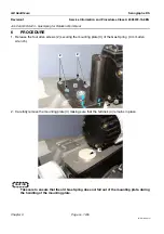
5. For each of the three securing nuts in turn (ratchet wrench with 11 mm socket (Arm covers) or 6 mm
socket (Head covers)):
-
Remove the nut. Apply some thread locking compound (Loctite 243 or equivalent) to the threaded
pin.
-
Refit the nut and tighten it using finger pressure. When correctly secured, the elastomer surface
of the keypad must remain in full contact with the inner side of the cover when buttons are
pressed, but there must be no deformation of the elastomer.
! Notice:
When the keypad is correctly fitted, the rear side of the keypad (black magnetic surface) must be
flat. Any deformation of the keypad board can cause damage.
6. When the installation of the keypads on the covers is complete, fit the covers in place temporarily on
the Tube Head and/or Arm. This allows the functional checks of keypad operation to be made before
completion. For example, install only the minimum number of securing screws required to ensure that
covers do not fall, and use masking tape to prevent unwanted movement.
! Notice:
1. Apply only moderate pressure when connecting a cable to a keypad, to avoid damage to the
connector. The connector is soldered in its position at right angles to the keypad board surface.
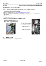
2. When reconnecting keypad cables and installing covers, ensure that the cables are correctly po-
sitioned as described in
Job Card D/R A215 - Arm Control Keypad Cables
.
7. With the compression paddle out of compression, check that all four arm rotation control buttons are
operational.
For each button, check that light or firm pressure gives the correct rotation, and that rotation stops
when the pressure is released. Refer to
Job Card ELE A015 - Gantry Functional Checks
, for a full list of these checks.
7
COMPLETION
When all functional checks have been completed successfully, complete the installation of the covers.
(see
or


