GE Healthcare
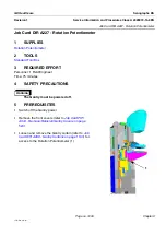
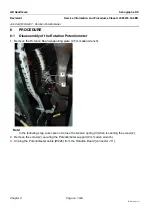
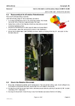
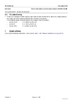
Senographe DS
Revision 1
Service Information and Procedures Class A 2385072-16-8EN
Job Card D/R A229 - Rotation Brake
Page no. 1249
Chapter 9
JC-DR-A-229.fm
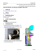
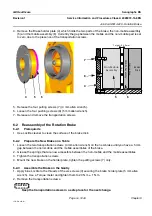
4. Remove the Brake holder plate (4) which holds the two parts of the brake; the non-mobile assembly
(5) and the mobile assembly (6). Currently the gap between the mobile and the non-mobile part is set
to zero due to the presence of the transportation screws.
5. Release the four pulling screws (7) (4 mm allen wrench).
6. Loosen the four pushing screws (8) (5 mm allen wrench).
7. Release and remove the transportation screws.
6-2
Reassembly of the Rotation Brake
6-2-1
Prerequisite
•
Use Loctite cleaner to clean the surface of the brake disk.
6-2-2
Prepare the New Brake on a Table
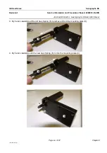
1. Loosen the two transportation screws (4 mm allen wrench) on the new brake until you have a 5 mm
gap between the non-mobile and the mobile assemblies of the brake.
2. Grease the springs that are now accessible between the non-mobile and the mobile assemblies.
3. Tighten the transportation screws.
4. Mount the new brake on the holder plate, tighten the pulling screws (7) only.
6-2-3
Assemble the Brake on the Gantry
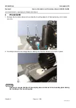
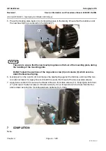
1. Apply blue Loctite to the threads of the six screws (3) securing the brake holder plate (5 mm allen
wrench). Use a Torque meter and tighten them to 20 N.m ± 1 N.m.
2. Remove the transportation screws.
CAUTION
Keep the transportation screws in a safe place for the next change.
4
5
6
Brake
D isk
N on
‐
M obile
Assem bly
Mo
bile
Asse
mbly
GA
P
Fric
tion
Are
a
Target:
0.15
m m
7
8
5
6
4

