


GE Healthcare
Senographe DS
Revision 1
Service Information and Procedures Class A 2385072-16-8EN
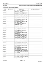
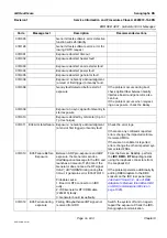
ERR SUB A001 - Generator Error Messages
Page no. 831
Chapter 9
ERR-SUB-A-001.fm
ERR SUB A001 - Generator Error Messages
Chapter 9
1
INTRODUCTION
This Job Card lists error codes generated by the Generator sub-system and displayed on the X-ray Con-
sole. Each message can contain two codes, the
User error code
and the
Service error code
(refer to the
explanation below). Error codes containing a Service Error Code are listed here; codes containing a
User Error code are listed in the
Senographe DS Operator Manual
. Many messages contain both, and
appear in both manuals.
Refer to Section 3
Error Code Structure
for an explanation of the error code display.
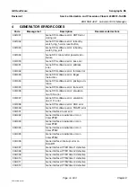
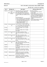
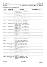
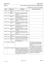
Section 4
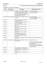
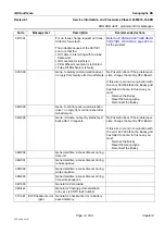
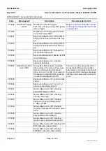
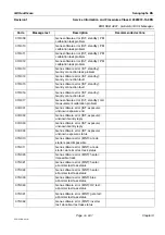
Generator Error Codes
lists the error codes, with corresponding error descriptions. Where pos-
sible (mainly for recently developed codes), the list also includes the text of a displayed error message,
and suggestions for corrective action.
2
HOW TO VIEW THE ERROR LOG
Errors reported by the Generator sub-systems are recorded in a common system error log which also
contains error messages generated by the AWS and IDC.
To view the error log content, right click the AWS Screen background; select
Service Tools/Service
Desktop/Error Log
from the drop-down menu.
3
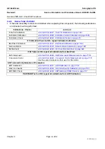
ERROR CODE STRUCTURE
Error codes are displayed on the X-ray Console in the format shown here:.
•
The User Error Code is the code given in the
Senographe DS Operator Manual
. It is easy to use and
communicate, and gives sufficient information for use by the Operator.
It includes a code for the type of error (
a
) and a message number (
bb
). The example given, E55, indi-
cates that a tube inhalation fault has occurred which caused exposure inhibition,
-
a
: Type of error:
I: Warning; exposure not inhibited.
S: Warning; exposure inhibited.
E: Fault; exposure inhibited.
K: Fault; power shut down for safety.
-
bb
: Message number indicating the origin of the fault.
•
The Service Error Code is the code used in this document; it gives more information, and is recom-
mended for use in GE internal communication. It includes two reference codes:
-
ccc
: Indicates the affected subassembly (hardware or software). The example given, 161, indi-
cates a tube housing fault.
-
ddd
: Indicates the origin of the fault The example given, 013, indicates that no reference crossing
was detected during tube movement.
E
5
5
1
6
1
0
1
3
Error text
a
bb
ccc
ddd
User error code
Service error code


