Chapter 7
Page no. 680
JC-ELE-A-028.fm
GE Healthcare
Senographe DS
Revision 1
Service Information and Procedures Class A 2385072-16-8EN
Job Card ELE A028 - Collimation Checks
7
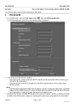
PROCEDURE
7-1
Exposures: Mo/Mo and Rh/Rh
7-1-1
X-ray to Light Field Tests
1. Both the Mo and Rh X-ray sources must be tested. Therefore, perform steps 1 through 7 for the large
focal spot for both the Mo and the Rh anode tracks.Install the Bucky on the image receptor.
2. Place the Radiation Protection Plate on the surface of the Bucky. Each side of the Radiation Protec-
tion Plate must extend about 4 cm beyond each edge of the light field.
CAUTION
The X-ray doses used in this procedure can saturate the image receptor if the Radiation
Protection Plate is not used and not correctly positioned. If the Radiation Protection Plate
does not completely cover the field of view, a ghost image may be imposed on the digital
image receptor at the edge of the Radiation Protection Plate. Ensure that the entire field of
view of the light field is covered by the Radiation Protection Plate.
Note:
To achive better contrast of the edge of the light field, it is recommended to tape a sheet of white
paper to the top of the aluminum attenuator.
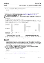
3. Verify that the collimator is in the maximum field size setting.
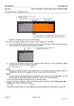
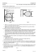
4. Label each of the four XR-M film strips corresponding to the anode track (Mo or Rh), and the field
edge (CW - chest wall, Ant - anterior, L - left, R - right) being tested. In the example below, the XR-M
film strip is labelled for the Mo anode track, and the chest wall edge.
Anode track being tested : Mo or Rh
Light field edge being tested : Right (R),
Left (L), anterior (Ant), or chest wall (CW)

