


GE Healthcare
Senographe DS
Revision 1
Service Information and Procedures Class A 2385072-16-8EN
Pre-Installation System Requirements
Page no. 335
Chapter 4
Chap-Pre-Requirements.fm
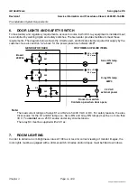
5-2. Room Power Supply
! Notice:
Line power to the Senographe system must be supplied through a suitable circuit breaker (see sec-
tion
The circuit breaker must be accessible to allow it to be opened rapidly in case of emergency. An
indicator light must be provided to indicate that power is present.
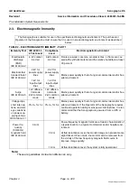
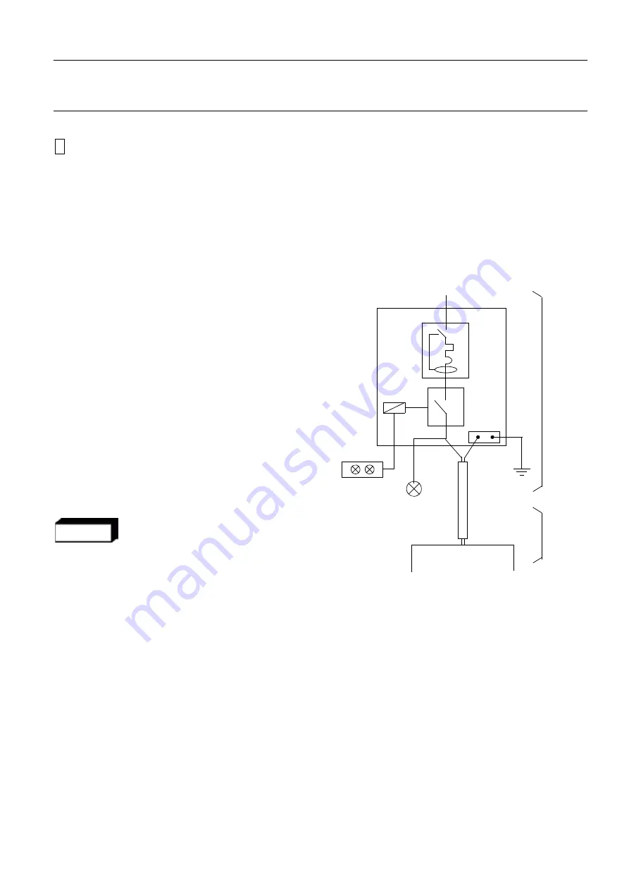
The diagram given here outlines a suitable supply system and indicates items to be provided and
installed by the customer electrician. Refer to the following sections for more information.
Legend:
-
PDB: Power distribution box supplying AC
power to the Senographe system equipment.
-
DCB: Differential circuit breaker (thermomag-
netic).
-
MC: Main contactor. Manual switch to be acces-
sible for emergency use.
-
PB: Remote control for main contactor; ON/
OFF impulse push-buttons, lockable ON/OFF,
with indicator lights (Red = ON, Green = OFF).
To be located near access door, 1.5 m
(59 inches) above the floor.
-
LMP1: Red power presence indicator light (con-
tinuous glow or flashing), located above access
door; bulb 30 V, 25 W max.
-
Line Supply Cable, which comprises of two sup-
ply wires (FW) and a ground cable (Gnd) —
3 x 5.32 mm².
WARNING
The Line Supply Cable from the Generator
must be internally and permanently con-
nected to the hospital power distribution
box, and cannot be externally connected to
the power distribution box via a plug. The
internal and permanent connection must be
made in a way such that the Line Supply
Cable can only be disconnected by use of a
tool.
-
Generator Cabinet.
5-2-1.
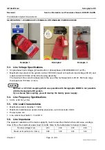
Lockable LOTO Enabled Power Sources
Lockable LOTO enabled power sources must be made available to the following:
•
the Line Supply Cable going from the room Mains Distribution Panel and the Generator
•
the Status Lamps power cables going from the room door to the Generator
Examples of LOTO enabled lockable power sources include those with lockable disconnecting switches
(see example 1 and example 2 in Illustration 1), or lockable breakers (see example 3 in Illustration 1).
Generator Cabinet
line input
AC supply
DCB
MC
PB
LMP1
FW
Gnd
PDB
Line
Su
pply
R
es
pons
ibility
of
cus
tomer’s
electrician
Responsibility
of
GEMS
FE
Cable


