


GE Healthcare
Senographe DS
Revision 1
Service Information and Procedures Class A 2385072-16-8EN
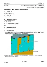
Job Card PHY A009 - Opposite Side Rotative Arm Installation
Page no. 423
Chapter 6
JC-PHY-A-009.fm
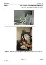
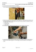
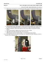
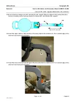
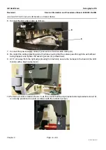
c. Attach the top two screws (17) to secure the top of the rotative arm support (5 mm allen wrench).
d. Carefully pull the acrylic support block to remove it from the two threaded rods. Unscrew the two
threaded in an anti-clockwise direction to remove them from the Control Station framework.
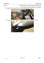
e. Attach the bottom two screws (18) to secure the top of the rotative arm support (5 mm allen
wrench).
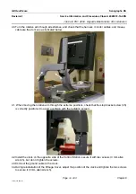
f. Use the torque wrench to tighten the four screws to 9.5 Nm
±
0.5 Nm.
g. Apply Blue Loctite 243 around the heads of the four screws.
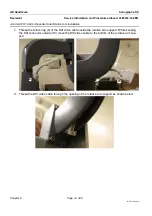
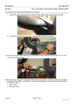
At this stage you cannot re-route the cables. You must change the stop bracket.
14. Turn the allen screw (19) at the joint of the rotative arm clockwise 540° (three full turns), but do not
remove it (2.5 mm allen wrench).
17
18
19


